Radial and Axial Thrust: The Forces That Dictate Pump Reliability
Every centrifugal pump generates two fundamental types of hydraulic load: radial thrust (perpendicular to the shaft axis) and axial thrust (parallel to the shaft axis). These forces are invisible during normal operation, yet they are the dominant factors determining bearing life, seal reliability, and the allowable operating range of the pump. Understanding where these forces come from and how to manage them is essential for anyone who specifies, maintains, or troubleshoots ANSI process pumps.
Why Hydraulic Loads Matter
A pump running at BEP with balanced hydraulic loads may deliver 50,000+ hours of bearing L10 life. The same pump running at 30% of BEP, where radial thrust can double or triple, may see bearing life drop below 10,000 hours. The pump did not change—the hydraulic loads did.
Radial Thrust: What Causes It and How It Damages Pumps
Origin of Radial Thrust
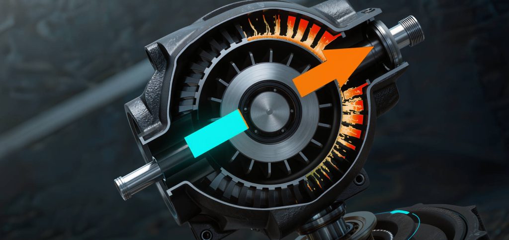
In a single-volute pump (the standard ANSI B73.1 design), the volute is designed to collect fluid uniformly around the impeller periphery at one specific flow—the BEP. At BEP, the pressure distribution around the impeller is approximately uniform, and radial thrust is minimal. Away from BEP, the pressure distribution becomes asymmetric: at low flows, pressure builds up near the cutwater and drops on the opposite side; at high flows, the pressure gradient reverses. This pressure asymmetry creates a net radial force on the impeller that is transmitted through the shaft to the bearings.
The magnitude of this force can be substantial. For a typical ANSI 3×2-10 pump at 30% of BEP flow, radial thrust can reach 1.5-2× the value at BEP. For larger pumps operating far to the left of BEP, the radial force can exceed 1,000 pounds—a load that dramatically shortens bearing life.
How Radial Thrust Affects the Shaft and Bearings
Radial thrust deflects the pump shaft. Excessive shaft deflection—more than 0.002 inches at the seal faces for most ANSI pump designs—causes the mechanical seal faces to open and close with each shaft revolution, accelerating seal wear by orders of magnitude. The same deflection overloads the radial bearing (typically a deep-groove ball bearing at the wet end and a double-row angular contact bearing at the drive end in ANSI pumps), causing fatigue spalling.
Axial Thrust: The Force Along the Shaft
Origin of Axial Thrust
Axial thrust arises from the pressure difference between the front and back shrouds of the impeller. Because the suction eye reduces the pressure area on the front shroud while the back shroud sees full discharge pressure across most of its surface, a net force pushes the impeller toward the suction. In a single-stage ANSI pump, this thrust is typically 200-800 pounds depending on pump size and developed head.
How Axial Thrust Is Managed
ANSI pump designs use several methods to manage axial thrust:
- Back wear rings and balance holes: The most common approach. A wear ring on the back shroud (same diameter as the front wear ring) creates a balance chamber. Balance holes through the impeller back shroud allow pressure equalization. This reduces—but does not eliminate—net axial thrust.
- Back pump-out vanes: Small radial vanes cast into the back shroud act as a secondary impeller, reducing the pressure in the stuffing box and generating a counter-thrust. These are effective but add friction and slightly reduce efficiency.
- Thrust bearings: The residual axial thrust (typically 100-300 pounds after hydraulic balancing) is carried by the thrust bearing, usually an angular-contact ball bearing pair at the drive end.
How Operating Conditions Change Hydraulic Loads
| Operating Condition | Radial Thrust | Axial Thrust |
|---|---|---|
| At BEP | Minimum—uniform pressure distribution | Design value—balanced by wear rings/holes |
| Below 50% BEP | 1.5-3× BEP value—highly asymmetric | Slightly reduced (lower head) |
| Above 120% BEP | 1.5-2× BEP value—reversed gradient | Increased (higher flow) |
| Worn wear rings (2× design clearance) | No direct effect | Increases due to reduced balance chamber effectiveness |
The practical implication: operating away from BEP increases radial thrust. Worn wear rings increase axial thrust. Both reduce bearing life. The cause of a premature bearing failure is rarely the bearing itself—it is the hydraulic load that the bearing was asked to carry.
Key Takeaways
- Radial thrust is minimal at BEP and increases significantly away from BEP—up to 2-3× at very low flow. This is the primary mechanism by which off-BEP operation destroys bearings and seals.
- Axial thrust is managed by back wear rings, balance holes, and pump-out vanes. When wear rings wear, axial thrust increases, overloading the thrust bearing.
- Shaft deflection from excessive radial thrust destroys mechanical seals—the deflection causes the seal faces to open and close with each revolution.
- If bearings are failing prematurely despite good alignment and lubrication, check the pump’s operating flow relative to BEP—hydraulic overload is often the root cause.