
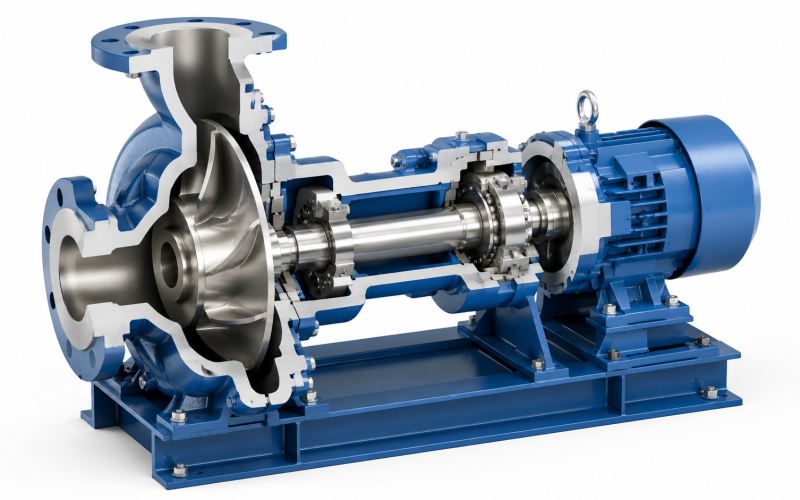
After more than a decade manufacturing ANSI B73.1 process pumps and replacement wet-end components, we’ve observed a consistent pattern: most pump selection mistakes don’t stem from misunderstanding how centrifugal pumps work — they come from overlooking the details that actually drive operating costs. Material compatibility under real process conditions — not just the main chemical component — the hidden cost of running far from the best efficiency point, and suction piping that quietly cavitates the impeller. This guide translates that factory-floor and field-service experience into a practical framework for industrial buyers and maintenance engineers evaluating horizontal centrifugal pumps.
Horizontal centrifugal pumps move roughly 70% of all industrial fluids, and their dominance isn’t accidental. The configuration offers easier installation and maintenance access than vertical designs, a broader range of available sizes and materials, and a century-plus track record of reliable service. But the category spans single-stage and multi-stage designs, end-suction and between-bearing arrangements, volute and diffuser casings, and dozens of metallurgy options — and the combination you choose directly affects your operating costs, maintenance intervals, and production uptime.
How a Horizontal Centrifugal Pump Works — and What Typically Goes Wrong
The operating principle is straightforward: a rotating impeller throws fluid outward by centrifugal force, converting mechanical energy from the motor into kinetic energy in the fluid. The volute casing then converts that velocity into pressure as the flow path expands toward the discharge nozzle. The low pressure created at the impeller eye continuously draws more fluid in from the suction line, establishing steady flow.
What textbooks rarely cover are the real-world failure modes. In our factory’s teardown analyses of pumps returned from the field, three root causes dominate: (1) chronic operation below 50% of BEP flow — the resulting hydraulic radial loads destroy bearings and mechanical seals within months, regardless of component quality; (2) material incompatibility that looks fine on a corrosion data sheet but fails under actual process conditions — temperature cycling, trace chlorides, abrasive fines, or transient pH swings that never appear in the design basis; and (3) inadequate suction conditions — insufficient NPSH margin accounts for roughly a third of the cavitation-damaged impellers and casings we inspect. Understanding the principle matters less than understanding what makes it go wrong.
Major Horizontal Centrifugal Pump Configurations
End-Suction Pumps
The workhorse of the process industries. Fluid enters axially through a nozzle on the front of the casing and discharges radially from the top. The ANSI B73.1 standard governs end-suction chemical process pump dimensions, which means pumps built to this standard share identical mounting footprints, nozzle locations, and shaft centerline heights across manufacturers — a genuinely valuable feature when you’re replacing a pump without wanting to modify piping or baseplates.
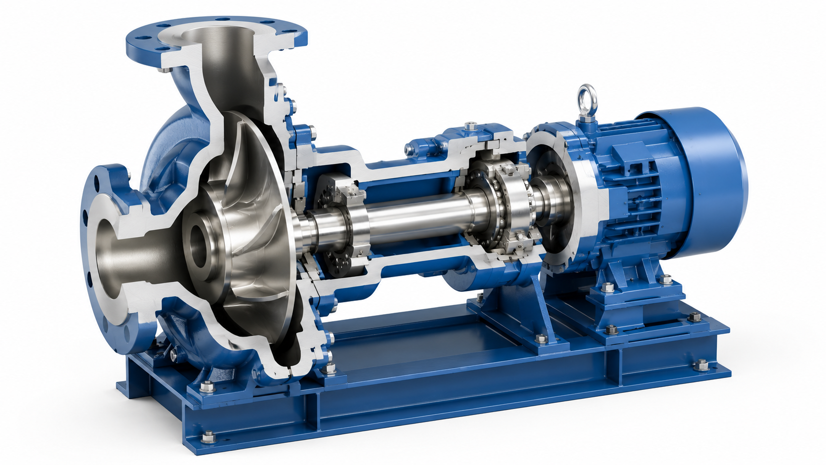
End-suction ANSI pumps handle the broadest range of chemical process applications — acids, caustics, solvents, heat transfer fluids — up to approximately 500 HP. For plants running Goulds 3196, Durco Mark III, or similar ANSI-frame equipment, dimensionally interchangeable replacement components are available in advanced metallurgies including CD4MCuN, Hastelloy C-276, Alloy 20, Titanium, and 316SS, matching OEM fit without the extended OEM lead times.
Horizontal Split-Case Pumps
The casing splits along the horizontal centerline of the shaft. Remove the upper half, and the entire rotating assembly — shaft, impeller, bearings, and seals — is accessible for inspection without disturbing suction or discharge piping. This design feature alone makes split-case pumps the standard for high-flow water services where uptime is critical: municipal water supply, cooling tower circulation, and fire pump systems.
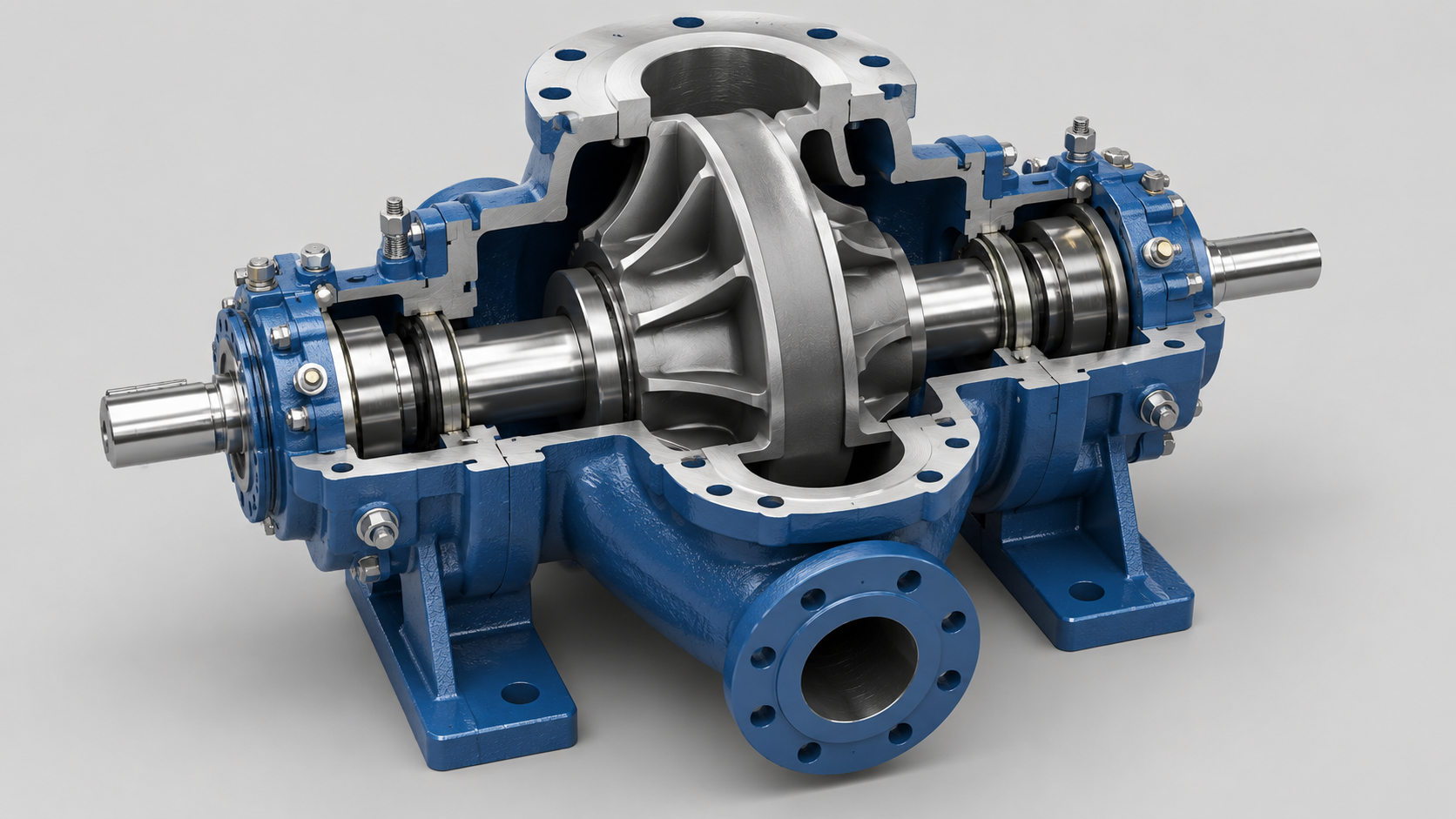
Most split-case pumps use a double-suction impeller — fluid enters from both sides, balancing axial thrust hydraulically and eliminating the need for heavy-duty thrust bearings. This is the kind of design detail that separates pumps that run 20 years between overhauls from those that eat bearings annually.
Multi-Stage Pumps
Multiple impellers are arranged in series on a common shaft, with each stage contributing its pressure increment to the total discharge head. Where a single impeller tops out around 200–250 psi, multi-stage horizontals push past 1,000 psi for boiler feed water, reverse osmosis membrane feed, pipeline booster stations, and high-pressure industrial washdown systems.
The trade-off is complexity: more impellers mean more wear rings, more interstage bushings, and more potential leak paths. A multi-stage pump correctly sized to operate near its BEP can run for years between overhauls. One oversized “for safety margin” and running at 30% of BEP will destroy its balance drum or disk within months — a pattern we encounter regularly in boiler feed applications where “future expansion” assumptions never materialized.
Design Features That Directly Affect Your Operating Costs
- Impeller type: Closed impellers deliver maximum efficiency with clean fluids. Semi-open impellers tolerate moderate solids and allow clearance adjustment as wear occurs. Open impellers handle trash and stringy solids — common in wastewater — at the cost of lower hydraulic efficiency. This choice directly impacts your power bill and maintenance schedule.
- Casing design: Volute casings are simpler and less expensive. Diffuser casings offer better efficiency near the design point and reduce radial load at off-design flow conditions — worth the premium in multi-stage and high-energy services.
- Shaft sealing: Mechanical seals are standard for most industrial applications. Component seals let you reduce seal inventory across pump sizes; cartridge seals eliminate installation measurement errors. Gland packing remains practical for large shaft diameters, abrasive slurries, or services where a small controlled leak is acceptable.
- Bearing arrangement: Grease-lubricated ball bearings serve most pumps under 100 HP. Oil-lubricated bearings run cooler in the 100–500 HP range. Above 500 HP, sleeve bearings with ring-oil lubrication become standard. Undersized bearings are a common cost-cutting measure in low-bid pumps — if reliability matters to your process, ask for the L10 bearing life calculation.
- Materials of construction: The most frequent selection error we see. 316SS handles many chemicals but pits rapidly in chloride environments above approximately 50°C. CD4MCuN (a duplex stainless steel) provides far better chloride resistance. Hastelloy C-276 handles oxidizing acids. Alloy 20 handles sulfuric acid. Titanium handles wet chlorine and seawater. The fluid chemistry — including trace contaminants and temperature excursions — determines the metallurgy, not just the primary process component listed in the P&ID.
Industrial Applications and Material Selection Reference
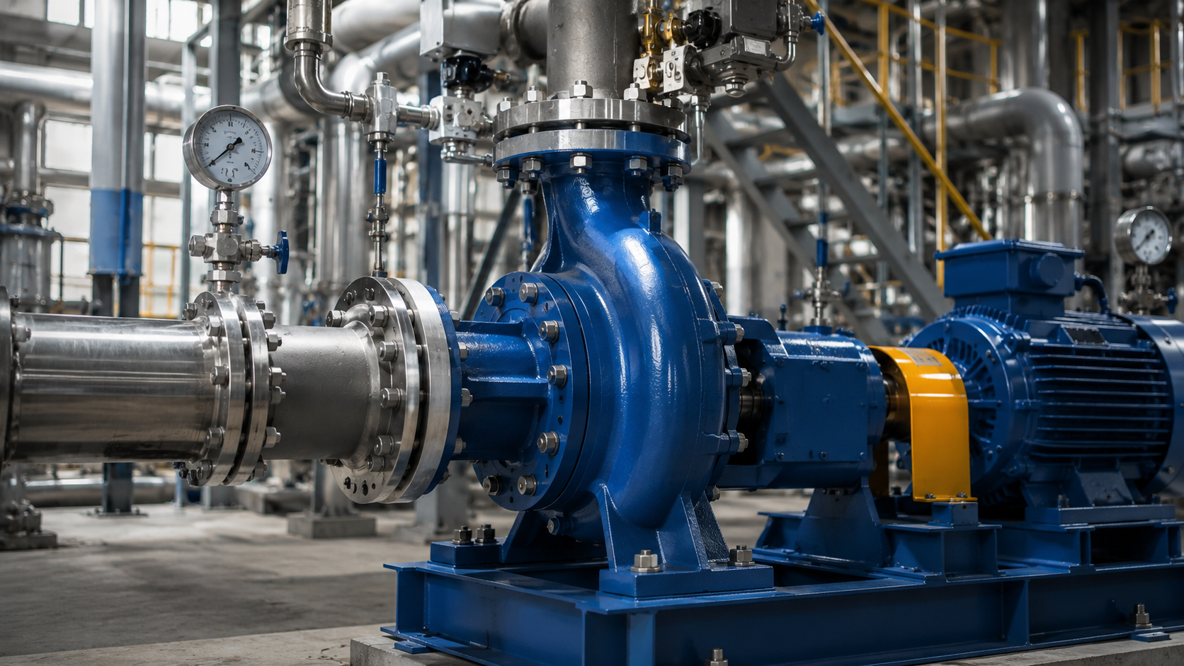
The following table matches common industries with the typical pump configuration and — critically — the materials that survive in each service environment. These recommendations reflect real field experience across hundreds of installations, not generic textbook guidelines:
| Industry | Application | Typical Configuration | Key Selection Materials |
|---|---|---|---|
| Chemical Processing | Process fluid transfer (acids, caustics, solvents) | ANSI B73.1 end-suction | 316SS, CD4MCuN, Hastelloy C-276, Alloy 20, Titanium |
| Water & Wastewater | Raw water supply, distribution, effluent handling | Split-case, end-suction | Ductile iron, 316SS, CD4MCuN (chloride-rich wastewater) |
| Oil & Gas | Crude transfer, product pumping, produced water | API 610 end-suction, between-bearing | Carbon steel, 316SS, Duplex SS (H₂S service per NACE MR0175) |
| Power Generation | Boiler feed, condensate return, cooling water | Multi-stage, split-case | Carbon steel (boiler feed), 316SS (condensate), Bronze-fitted (cooling water) |
| HVAC | Chilled/hot water circulation | End-suction, close-coupled | Cast iron, Bronze-fitted, 316SS (glycol systems) |
| Mining | Slurry transfer, dewatering, process water | Heavy-duty end-suction, rubber-lined | High-chrome iron (slurry), Natural rubber-lined, CD4MCuN (acid mine drainage) |
Performance Optimization: Practical Steps That Reduce Lifetime Costs
- Size for the operating point, not the “maybe someday” flow: A pump running within 70–120% of its BEP consumes less power per gallon pumped and lasts substantially longer. An oversized pump wastes energy continuously — the power bill difference often exceeds the purchase price premium of a correctly sized unit within two years. If process expansion is uncertain, size for today’s conditions and plan space for a future parallel unit.
- Use a VFD when system demand varies: The affinity laws work in your favor: reducing pump speed by 20% cuts power consumption by roughly 50%. Throttling a constant-speed pump wastes the energy already consumed by the motor — it’s pure operating cost with zero return.
- Get the suction piping right: Use eccentric reducers with the flat side up to prevent air pockets. Maintain 5–10 pipe diameters of straight run upstream of the suction flange. Keep NPSH available at least 1 meter above the pump’s NPSH required across the entire operating range — not just at the design point.
- Laser-align to within 0.002 inches: Soft-foot correction and precision shaft alignment extend seal and bearing life more than any premium component upgrade. We regularly inspect pumps with high-end cartridge seals that failed prematurely because the pump and motor were aligned by feel rather than by laser.
- Trend, don’t just inspect: Vibration spectra, oil analysis, and performance curve tracking catch developing problems weeks or months before they cause unplanned downtime. A $500 condition monitoring investment typically pays for itself by preventing one avoided emergency shutdown.
Where Horizontal Centrifugal Pump Technology Is Heading
The fundamental horizontal centrifugal design has been stable for decades, but the technology surrounding it continues to evolve. IoT-enabled pump controllers now monitor vibration spectra, bearing temperature, seal chamber pressure, and performance deviation from the baseline curve — alerting maintenance teams to developing issues before a failure cascades. CFD-optimized impeller hydraulics squeeze an additional 3–5% efficiency from designs that were already well-refined, a gain that compounds meaningfully across thousands of operating hours. Advanced alloys and engineered composites continue expanding the chemical compatibility envelope, particularly for corrosive services where traditional metallic options were limited.
For the industrial buyer or maintenance engineer, the core task remains unchanged: match the pump configuration to the process, select materials that survive the real fluid chemistry — trace contaminants and temperature excursions included — and operate near the BEP. The tools for doing that matching have improved, but the fundamentals still determine whether you get five years or five months between overhauls.
💡 Evaluating pump materials or confirming interchangeability for your current ANSI fleet? Discuss your application with our engineering team →