
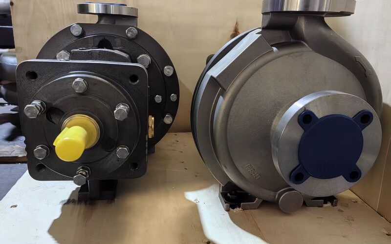
Why Impeller Clearance Matters
Every centrifugal pump impeller operates with a designed running clearance between its rotating surfaces and the stationary casing walls. Over time, wear — from abrasion, erosion, or cavitation — progressively opens this clearance. As the gap widens, an increasing portion of the pumped fluid recirculates from the high-pressure discharge side back to the low-pressure suction side through the clearance gap, rather than exiting through the discharge nozzle. This internal recirculation is pure energy waste: it consumes motor horsepower without producing useful flow, causing the pump’s overall efficiency to decline — sometimes by 5-10 percentage points on smaller frame sizes — and drive up energy costs.
The solution is routine impeller clearance adjustment, a relatively simple mechanical procedure that restores the designed gap and returns the pump to its original hydraulic performance. However, the how of this adjustment differs fundamentally between the two dominant ANSI pump platforms: the Goulds 3196 and the Durco Mark III. Understanding both methods is essential for any maintenance engineer who works across a mixed pump fleet — and for procurement managers evaluating the maintainability of aftermarket replacement components.
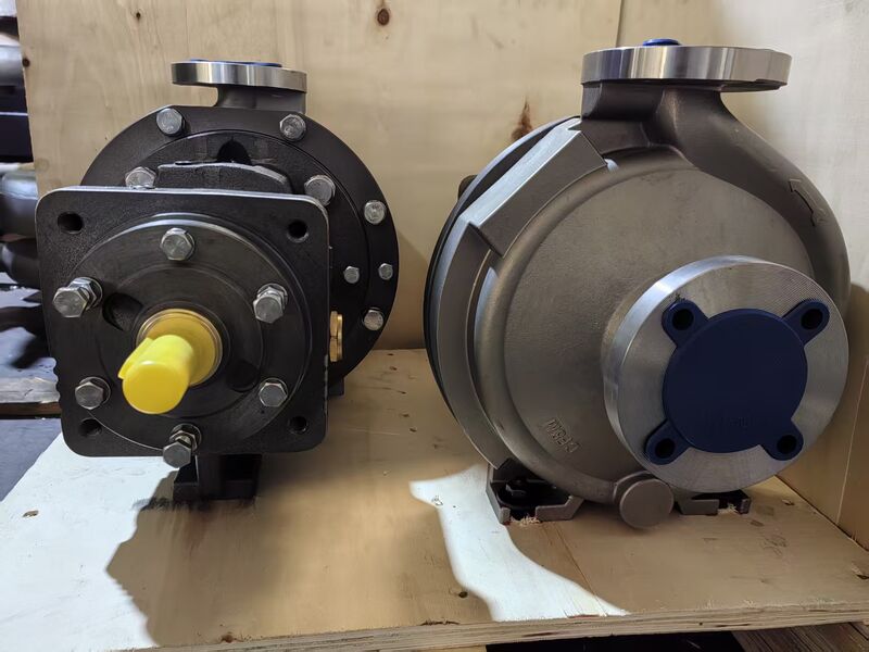
Goulds 3196 Impeller Clearance Adjustment: Front Casing Method
The Goulds 3196 uses a front-side clearance adjustment philosophy. The impeller is an open design, and the critical clearance is between the impeller vane tips and the front casing (volute) cover.
⚠️ Quality & Compliance Assurance
All pumps and components from ANSI Pumps Pro are manufactured to ASME B73.1 dimensional specifications. Each shipment includes certified Material Test Reports (MTRs), CMM dimensional inspection reports, and hydrostatic test certificates (1.5× MAWP). 100% dimensional interchangeability guaranteed. Full material traceability from heat number to your receiving dock.
Step-by-Step Procedure
- Safety isolation: Complete Lockout/Tagout (LOTO). Confirm zero energy state. Drain and flush the pump casing per site hazardous material procedures.
- Loosen the bearing frame locking bolts that secure the bearing frame / adapter to the pump casing. Do not remove them — just break torque so the frame can slide.
- Mount a dial indicator on the bearing housing or shaft, with the indicator tip contacting the front casing cover. Zero the indicator.
- Advance the thrust bearing adjusting screw (located at the outboard end of the bearing housing) to push the entire rotor assembly toward the suction side. Continue until the impeller vane tips make light contact with the front casing — detected by a sudden increase in turning resistance when rotating the shaft by hand, or a “kick” on the dial indicator.
- Record the indicator reading at the contact point. This is your zero-clearance reference.
- Back off the adjusting screw by the manufacturer’s specified clearance — typically 0.015 inches (0.38 mm) for ambient-temperature services, or up to 0.025-0.030 inches for hot services (250°F / 120°C and above) to accommodate thermal expansion of the rotor relative to the casing.
- Lock the bearing frame in position. Rotate the shaft by hand to confirm free rotation without rubbing.
- Re-verify and adjust the mechanical seal compression — this is a critical step unique to the Goulds design. Because the entire rotor has moved axially relative to the seal chamber, the mechanical seal’s spring compression has changed and must be re-set to the seal manufacturer’s specification.
Key takeaway: The Goulds 3196 adjustment requires re-verification of the mechanical seal setting every time. Skipping this step is a common cause of premature seal failure after routine impeller clearance adjustment.
Durco Mark III Impeller Clearance Adjustment: Rear Cover Method
The Durco Mark III takes the opposite approach. Because the reverse vane impeller’s critical clearance is between the rear pump-out vanes and the rear cover (seal chamber / stuffing box cover), the adjustment is made at the back of the pump — completely independent of the front casing.
Step-by-Step Procedure
- Safety isolation: LOTO, drain, flush — same as above.
- Loosen the rear cover bolts that secure the seal chamber / stuffing box cover to the bearing frame adapter.
- Using the external jacking bolts (a distinctive feature of the Mark III design, located around the perimeter of the adapter), move the entire rotating assembly — shaft, bearings, and impeller — rearward (away from the pump casing) until the reverse vanes on the back of the impeller contact the front face of the rear cover.
- Measure the gap between the bearing housing flange and the adapter using feeler gauges. This is your zero-clearance reference.
- Advance the jacking bolts to push the rotor forward by the specified clearance — typically 0.015-0.020 inches. The feeler gauge should now slide into the gap with light resistance.
- Tighten the rear cover bolts to the specified torque. Rotate the shaft to confirm free rotation without rubbing at the reverse vanes.
- Done. The mechanical seal compression is completely unaffected — no re-setting required.
Key takeaway: The Mark III’s rear adjustment method is inherently faster (typically 15-20 minutes vs. 30-45 minutes for the Goulds) and eliminates the risk of inducing a seal failure through incorrect seal re-setting after adjustment. This is a significant maintenance-hour reduction in plants with large pump populations requiring quarterly or semi-annual clearance checks.
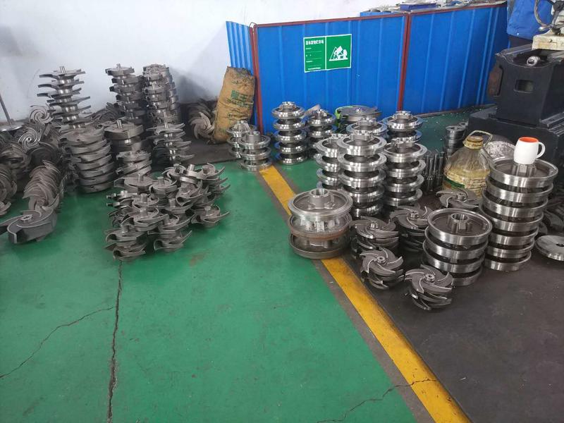
Head-to-Head Comparison: Front vs. Rear Adjustment
| Characteristic | Goulds 3196 (Front Adjustment) | Durco Mark III (Rear Adjustment) |
|---|---|---|
| Clearance reference surface | Front casing / volute cover | Rear cover / seal chamber face |
| Adjustment mechanism | Thrust bearing adjusting screw (outboard end) | External jacking bolts (perimeter of adapter) |
| Typical cold clearance | 0.015 in (ambient) to 0.030 in (hot service) | 0.015-0.020 in |
| Measurement method | Dial indicator on front casing | Feeler gauges at adapter flange gap |
| Mechanical seal affected? | YES — seal compression changes; re-setting mandatory | NO — seal is completely independent of this adjustment |
| Typical adjustment time | 30-45 minutes (including seal re-set) | 15-20 minutes |
| Risk of induced seal failure | Moderate — if seal re-set is skipped or incorrect | Very low — seal is never disturbed |
| Casing gasket disturbed? | No — casing remains bolted; front cover is static | No — casing remains bolted; only rear cover bolts loosened |
Impact on the Mechanical Seal: The Critical Distinction
The most operationally significant difference between these two adjustment methods is their relationship to the mechanical seal.
In the Goulds 3196, the mechanical seal’s stationary seat is mounted in the seal chamber (which is bolted to the casing / adapter), while the rotary unit is mounted on the shaft. When the entire rotor is moved axially during clearance adjustment, the rotary unit moves with it — changing the axial compression of the seal spring and the contact pressure between the stationary and rotating seal faces. If the clearance adjustment moved the rotor 0.015 inches forward and the seal was set with 0.125 inches of spring compression, the seal now has only 0.110 inches of compression — a 12% reduction. Conversely, if the adjustment is reversed, over-compression can cause excessive face heating and rapid wear. Either way, the seal must be re-measured and re-set.
In the Durco Mark III, the adjustment moves the rotor relative to the rear cover, but the seal chamber is integral with that rear cover — meaning the seal’s stationary and rotary components move together as a unit. The relative position between the seal faces does not change, and the spring compression remains at its factory-set or installer-set value. This is a deliberate and elegant design feature that directly reduces the probability of maintenance-induced seal failures — a category that, across the industry, accounts for an estimated 30-40% of all mechanical seal failures in the first 90 days after a pump repair.
Aftermarket Components: Full Compatibility with Both Adjustment Systems
Regardless of which adjustment philosophy your maintenance team is trained on and equipped for, the availability of high-quality, dimensionally accurate aftermarket components is essential for cost-effective pump fleet management.
At ansipumpspro.com, we manufacture and supply:
- Goulds 3196-compatible bearing frames with the front adjustment mechanism (thrust bearing adjusting screw), precision-machined to accept Goulds OEM or equivalent bearing sets and oil seals. Adapter flanges mate directly to existing Goulds casings.
- Durco Mark III-compatible bearing frames and adapters with the rear jacking bolt adjustment system, fully compatible with the Mark III rear cover / seal chamber interface and the reverse vane impeller clearance logic.
- Impellers, rear covers, seal chambers, and shaft sleeves for both pump families, available in the full range of standard and exotic alloy materials.
All components are manufactured to OEM-equivalent dimensional specifications, ensuring that the designed impeller clearance adjustment range — and the mechanical seal independence on the Mark III design — functions exactly as the OEM intended.
For technical inquiries or to request a cross-reference of your existing Goulds or Durco pump part numbers to our aftermarket equivalents, contact us at ansipumpspro.com/contact.
📋 Quick RFQ — No Registration Required
🔗 Related Reading
Quick-Reference: Impeller Clearance Adjustment by Brand
| Pump Brand | Adjustment Location | Method | Clearance Target | Time Estimate |
|---|---|---|---|---|
| Goulds 3196 | Front casing to bearing housing | Dial indicator on shaft; adjust bearing housing shims | 0.010-0.015″ | 30-45 min |
| Durco Mark III | Rear cover (stuffing box) to bearing housing | Micrometer thread on rear cover; rotate to set | 0.012-0.018″ | 15-20 min |
| Peerless 8196 | Similar to Goulds — front shim pack | Dial indicator; shim removal | 0.010-0.015″ | 30-45 min |
| Griswold 811 | Rear cover adjustment | Jacking bolts on bearing housing | 0.010-0.016″ | 20-30 min |
Critical: Always rotate the shaft by hand after adjustment to verify zero rub before startup. A dragging impeller on startup can destroy the mechanical seal in seconds.