
What ASME B73.1-2026 Actually Governs
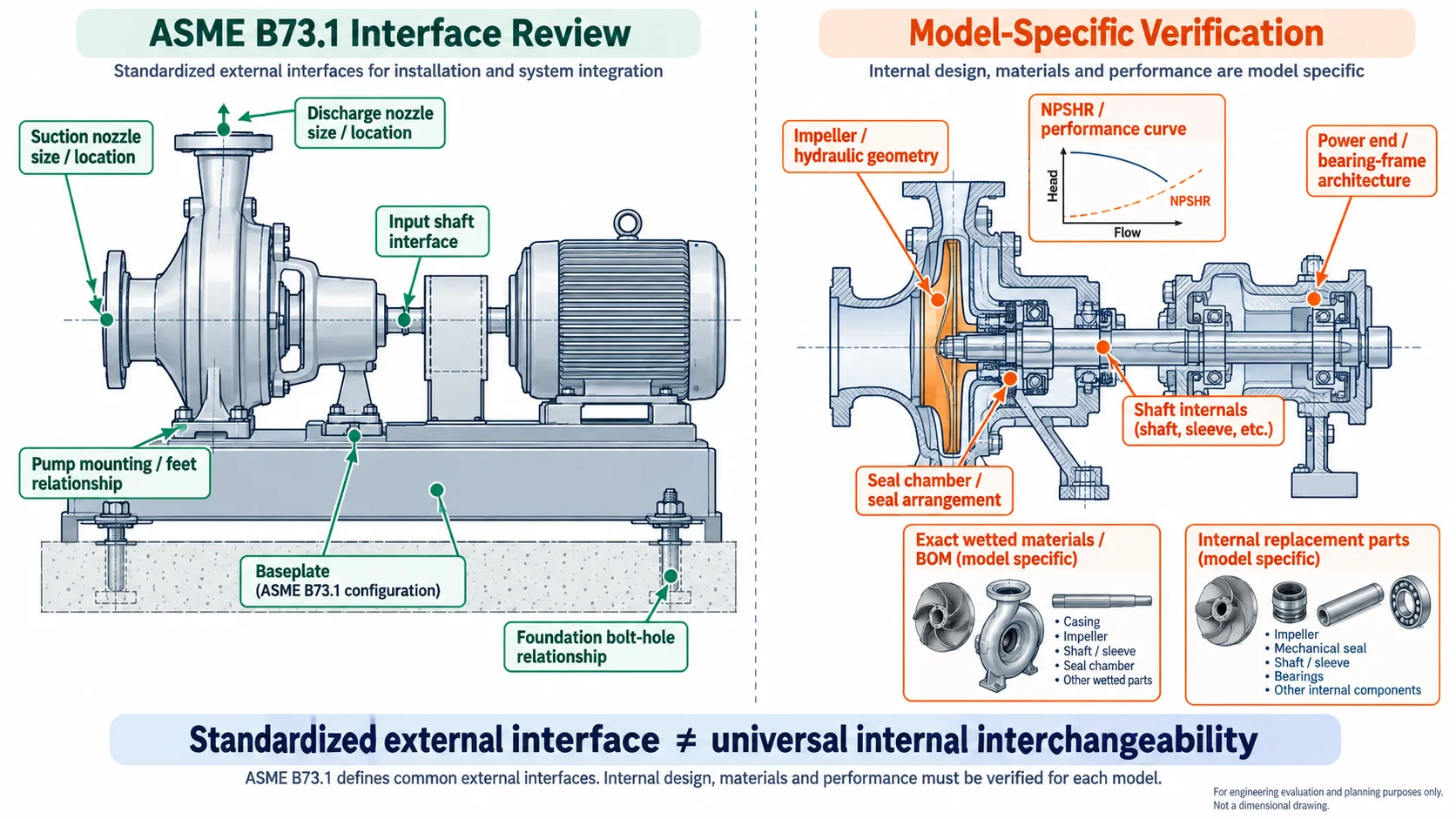
ASME B73.1 establishes a common design and dimensional framework for applicable horizontal, end-suction, single-stage, centerline-discharge chemical-process centrifugal pumps. For pumps carrying the same applicable standard dimension designation, the standard is intended to support dimensional interchangeability at defined installation interfaces such as mounting dimensions, suction and discharge nozzle size/location, input-shaft interfaces, baseplates and foundation-bolt relationships.
That does not mean two pumps with the same ANSI/ASME designation have the same hydraulic curve, NPSHR, impeller geometry, shaft, seal chamber, power end, materials or internal spare parts. Those items still require model-specific evidence.
Buyer rule
“B73.1 compliant” is the beginning of a replacement review—not the end of it. Treat the standard claim as evidence about the applicable design/dimensional framework, then separately verify hydraulics, materials, seal arrangement, internals and project-specific testing.
What Actually Changed in ASME B73.1-2026
The 2026 edition should be discussed from the published revision summary—not from inferred or marketing-style claims about tighter CNC tolerances or automatic test-grade changes. For procurement, the useful question is how each revision area changes what needs to be stated, reviewed or documented.
| Published 2026 revision area | Buyer / MRO implication |
|---|---|
| Thermoset and thermoplastic composites added to para. 4.2 | State the actual construction/material system; do not use a broad “polymer pump” label as the entire specification. |
| Low-temperature-limit guidance | Low-temperature service should include the operating/design temperature and applicable material/design review. |
| Additional gasket design-criteria details | Review the actual gasket/joint configuration rather than assuming a generic joint detail. |
| Impeller-balance figure | Where balance requirements are contractually relevant, define the required evidence and basis in the purchase specification. |
| Welded / flanged auxiliary-piping detail additions | Verify the actual piping/interface arrangement shown on the approved configuration. |
| Austenitic stainless-steel welding note | Material name alone is not a complete fabrication requirement; project welding requirements may still need to be stated. |
| Guard hazard-communication / seal-area guard material updates | Treat guarding as part of the documented delivered configuration, not an assumed site accessory. |
| New casing-temperature and bearing-temperature measurement sections | If monitoring or test documentation is required, specify what is measured and recorded. |
| New bearing-vibration measurement section | Define the required vibration measurement/test basis when it matters to acceptance or reliability review. |
| Fluoropolymer-lined metallic pumps added to section 6 | Do not transfer metallic-pump assumptions automatically to lined construction; verify the actual product architecture. |
| Vacuum-limit provisions for metallic and fluoropolymer-lined metallic pumps | Vacuum service requires explicit confirmation rather than a generic B73.1 compliance statement. |
| Table 7.2.2.3-1 revised / new Nonmandatory Appendix B | Use the current licensed edition for final contractual dimensions and requirements; this article is a buyer guide, not a replacement for the standard. |
Do not invent 2026 changes
This guide will not claim that B73.1-2026 universally tightened shaft TIR, standardized specific Plan 11/32/53A port dimensions, made one ANSI/HI 14.6 grade the default, or introduced a new universal grouting tolerance unless the licensed standard/project specification explicitly supports that statement.
Standard Dimension Designation Is Not the Same as an OEM Model or Frame Name
A standard dimension designation is part of the ASME B73.1 dimensional framework. An OEM model, bearing-frame name or product-family group is a manufacturer-specific identifier. They should not be merged into one classification system.
For replacement work, record all three where available. A matching standard designation can support external fitment review, but it does not prove that one manufacturer’s impeller, shaft, seal chamber or power end can be substituted into another manufacturer’s pump.
What B73.1 Can Help Verify—and What It Cannot Prove by Itself
Standardized Interfaces vs. Model-Specific Verification
Use the B73.1 interface framework to review external installation compatibility, then verify hydraulics, internals, materials and seals with model-specific evidence.
| Buyer question | B73.1 alone? | Additional evidence |
|---|---|---|
| Mounting dimensions | Within applicable standard scope | Approved GA / outline drawing |
| Suction/discharge nozzle size and location | Within applicable designation | Approved outline drawing |
| Baseplate / foundation relationship | Within applicable standard scope | Baseplate drawing / as-built check |
| Input-shaft interface | Within applicable standard scope | Approved dimensional drawing |
| Same hydraulic curve | No | Certified/proposed pump curve |
| Same NPSHR | No | Hydraulic data / test data as specified |
| Same impeller geometry | No | Model-specific drawing / BOM |
| Same shaft or seal chamber | No | Component / chamber drawings |
| Same metallurgy | No | Exact material specification / BOM |
| Same internal spare parts | No | Model / part-number / fitment verification |
For field replacement work, the separate ANSI pump interchangeability verification guide goes deeper into how standardized external fitment should be separated from internal compatibility. If a field survey is required, use the five ANSI pump interfaces to verify before approving a drop-in replacement.
Which Standard Answers Which Engineering Question?
| Standard / guideline | Primary question it answers | Procurement use |
|---|---|---|
| ASME B73.1-2026 | What chemical-process pump design/dimensional framework applies? | Specify applicable B73.1 scope/designation and verify controlled external interfaces. |
| ANSI/HI 14.6-2022 | How should hydraulic performance be tested and accepted? | State the required acceptance-test basis separately from a B73.1 dimensional claim. |
| ANSI/HI 9.6.1 | What NPSH margin should be reviewed? | Evaluate NPSH margin using the current guideline and manufacturer-supplied NPSHR basis. |
| ANSI/HI 9.6.2 | How should applied nozzle loads be assessed? | Review piping forces/moments where nozzle loads and reliability are part of the project. |
| API 610 | Is the project using an API petroleum/process-pump specification instead? | Do not substitute B73.1 and API 610 terminology as if the standards were interchangeable. |
For hydraulic acceptance details, use the dedicated ANSI/HI 14.6 pump acceptance testing guide. For piping loads, see the pump nozzle loads and piping-strain guide. When the project may belong in an API pump specification instead, review API 610 vs ASME B73.1.
B73.1 compliance does not select the HI 14.6 acceptance grade for you
If a factory hydraulic acceptance test is required, state the applicable ANSI/HI 14.6 requirement in the RFQ or purchase specification. Do not treat “ANSI compliant” as shorthand for a particular hydraulic-test grade.
What Evidence Should a Buyer Request Before PO Approval?
1. Identity
Manufacturer, model, size, equipment tag, applicable standard/designation and drawing revision.
2. Dimensional
Approved GA, nozzle locations, mounting, shaft interface, baseplate/foundation relationship.
3. Hydraulic
Flow, head, speed, impeller diameter, power, efficiency, NPSHR and proposed curve.
4. Material
Exact material specification/BOM plus MTR or PMI only where the contract/project requires them.
5. Acceptance
Inspection/test plan, hold or witness points, deviations and required release documentation.
MTR / PMI boundary
MTR and PMI can help verify what material was supplied. They do not prove that the alloy is suitable for the actual process chemistry, concentration, temperature, velocity or solids.
Six Steps From Existing Pump to an Approve / Hold Decision
Buyer Verification Workflow
Resolve fitment, hydraulics, materials and acceptance evidence before the purchase order is released.
Existing equipment
Nameplate, model, size, tag, drawings and field modifications.
Verify interface
Designation, mounting, nozzles, shaft and baseplate/foundation relationship.
Verify duty
Flow, head, RPM, trim, NPSHR and operating region.
Verify wet end
Exact material, seal chamber/arrangement and process-service evidence.
Define tests/docs
Inspection plan, required test basis, deviations and document package.
Approve / hold
Release only after exceptions and unresolved interfaces are documented.
Goulds 3196 and Durco Mark III: Use B73.1 as the Interface Framework, Not the Parts Cross-Reference
Both product families may appear in ASME B73.1 replacement projects. That does not make their impellers, shafts, seal chambers, power ends or other internal parts interchangeable simply because both are associated with ANSI chemical-process pump service.
When Should a Buyer Hold or Escalate a B73.1 Compliance Claim?
| Supplier / project condition | Buyer action |
|---|---|
| “ANSI compliant” but no edition/designation is identified | Request the exact standard basis and applicable designation before approval. |
| No approved GA / outline drawing | Hold dimensional-fit approval. |
| “Fits 3196 / Mark III because both are ANSI” | Require model-specific fitment evidence; do not accept the standard claim as internal-parts proof. |
| No hydraulic curve for the proposed configuration | Hold hydraulic approval until flow/head/NPSHR/power data are available. |
| Material described only as “Hastelloy” / “Alloy 20” | Request exact material grade/form/specification and component scope. |
| “ANSI tested” but no test standard/requirement is stated | Ask for the actual acceptance-test basis and required documentation. |
| Installed baseplate or piping was field-modified | Use as-built measurements; do not assume original standardized geometry remains intact. |
| Drawing revision conflicts with RFQ / PO | Resolve the controlled document revision before manufacturing release. |
Inputs to Lock Before Approving a Replacement Pump
ASME B73.1-2026 Buyer FAQ
Does ASME B73.1 make every ANSI process pump internally interchangeable?
No. B73.1 standardizes defined design and installation interfaces for applicable pumps. Internal parts such as impellers, shafts, seal chambers and power ends still require model-specific verification.
Does B73.1 compliance prove that a replacement has the same hydraulic curve?
No. Hydraulic performance must be verified from the proposed pump curve, duty point, speed, impeller configuration, NPSHR and other hydraulic data. A dimensional compliance statement is not a hydraulic guarantee.
Are ASME B73.1 and ANSI/HI 14.6 the same requirement?
No. B73.1 is a chemical-process pump design/dimensional specification framework. ANSI/HI 14.6 is a hydraulic-performance acceptance-test standard. If a performance test is required, specify that requirement separately.
Should every replacement-pump order automatically include MTR, PMI and hydrostatic certificates?
No. The required inspection, test and documentation package should be defined by the RFQ, purchase specification, ITP and project requirements. MTR/PMI can verify material identity when required, but they do not establish process suitability by themselves.
What should I request before approving an aftermarket ANSI pump replacement?
At minimum, verify the existing equipment identity, approved dimensional drawing, hydraulic duty/curve, exact materials, seal/interface requirements, required inspection/test scope and any documented deviations from the installed pump or project specification.
Technical Sources
- ASME — B73.1-2026, Specification for Horizontal End Suction Centrifugal Pumps for Chemical Process
- Accuris / ASME preview — B73.1-2026 published revision summary
- Hydraulic Institute — ANSI/HI 14.6-2022 Rotodynamic Pumps for Hydraulic Performance Acceptance Tests
- Hydraulic Institute — ANSI/HI 9.6.1 Rotodynamic Pumps Guideline for NPSH Margin
- Hydraulic Institute — ANSI/HI 9.6.2 Applied Nozzle Loads