
Start With the Service, Not the Impeller Label
Open, semi-open and enclosed impellers describe different hydraulic architectures. None of those labels alone approves a pump for a liquid. Start with the service, the required duty, the maintenance strategy and the architecture already installed.
Liquid condition
Clean liquid, suspended solids, crystals, fibers, abrasive particles, entrained gas, corrosion risk and shutdown deposits.
Hydraulic duty
Required flow, total head, speed, operating range, suction condition and the exact performance curve for the selected pump size.
Maintenance strategy
How wear is inspected, how running clearance is restored, what surfaces are replaceable and how often the pump can be opened for service.
Installed architecture
Casing, cover, shaft, hub, wear surfaces, direction of rotation, impeller-setting method and the components that will remain in service.
Open, Semi-Open and Enclosed: What Geometry Actually Changes
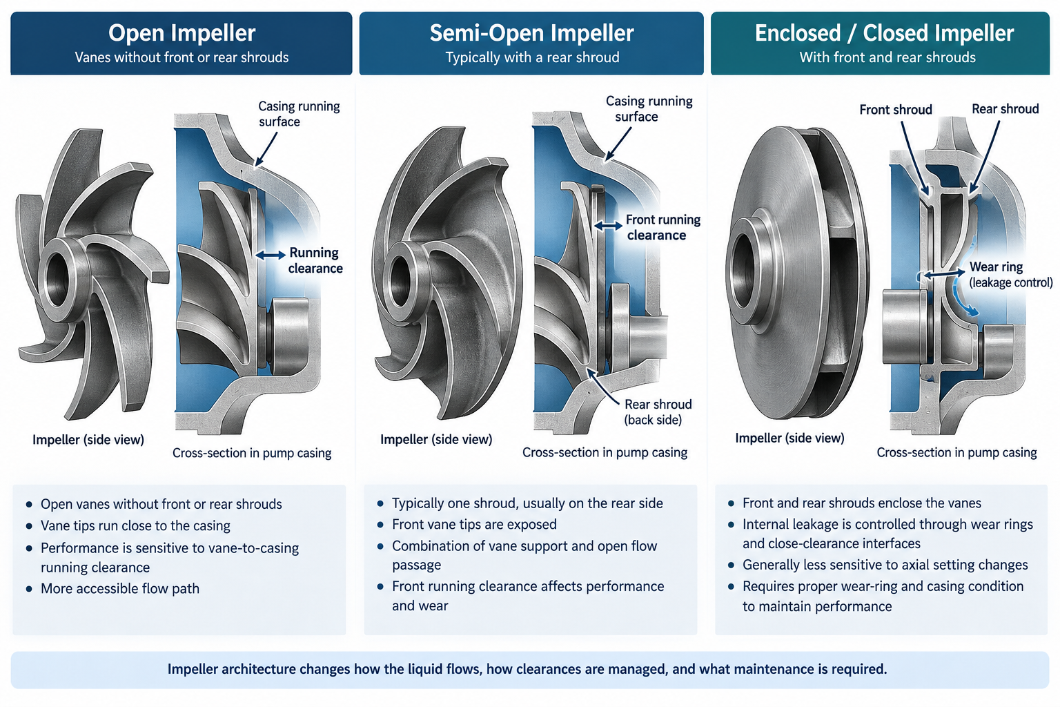
Hydraulic Institute distinguishes open, semi-open and enclosed impellers by their shroud arrangement. That geometry changes how running clearances are managed, where internal leakage develops as wear progresses and which surfaces must be inspected during maintenance.
| Architecture | Geometry | Main engineering consequence |
|---|---|---|
| Open | Vanes without enclosing front and rear shrouds | Hydraulic behavior can be sensitive to vane-to-casing running clearance and exposed-vane wear. |
| Semi-open | One shroud, commonly on the rear side, with one exposed vane side | Combines vane support with an exposed running-clearance side; the exact setting reference depends on the pump design. |
| Enclosed / closed | Front and rear shrouds enclose the vane passages | Internal leakage is commonly controlled through wear-ring or other close-clearance interfaces. |
A common dimensional process-pump framework does not make internal hydraulics, clearances or individual impellers interchangeable.
Clearance, Internal Leakage and Wear
As running clearances grow with wear, internal recirculation can increase and hydraulic performance can decline. The leakage path is architecture-specific: open and semi-open designs may depend strongly on vane-to-casing clearance, while enclosed designs commonly depend on wear-ring or other close-clearance interfaces.
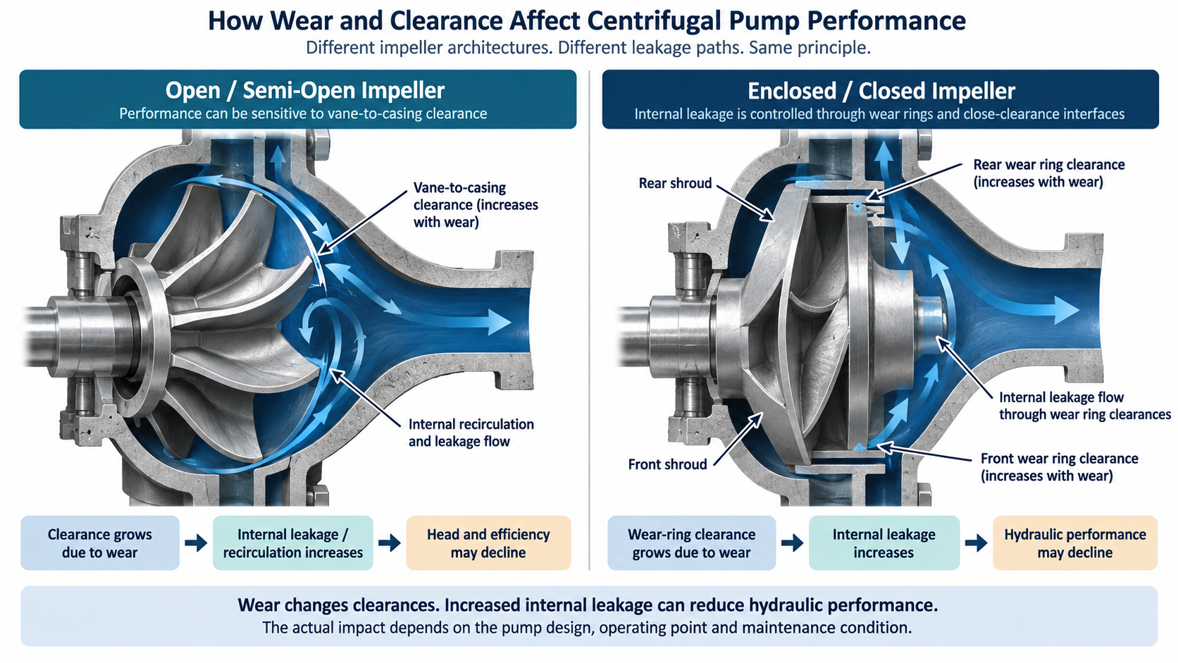
Running clearance grows as the vane or casing running surface wears.
More liquid can leak across the running interface instead of contributing to useful head.
The magnitude must be checked for the exact pump design and operating point.
Wear-ring or close-clearance interfaces enlarge as they wear.
The leakage-control surfaces no longer reproduce their as-new condition.
Use the applicable manufacturer limits and exact pump curve to judge the effect.
Do not copy a clearance value from another pump family. For platform-specific setting logic, use the Goulds 3196 vs Durco Mark III impeller-adjustment guide.
Solids Handling: Passage Geometry Matters More Than the Label
“Open impeller” is not a universal solids rating. Particle size, shape, concentration, abrasiveness, fibers, crystallization tendency, gas content and the complete casing-and-impeller flow path all affect the decision.
| Service condition | Architecture direction to investigate | Main risk to verify |
|---|---|---|
| Clean, stable liquid | Enclosed or other high-efficiency hydraulic designs may be attractive | Exact curve, operating point, wear interfaces and NPSHr |
| Light suspended solids | Open or semi-open may be considered | Actual solids passage, abrasion and running-clearance wear |
| Fibrous or clogging tendency | Open, semi-open or a specialized solids-handling geometry may be required | Real passage geometry, vane shape and casing path |
| Abrasive solids | Do not choose by shroud count alone | Erosion pattern, material, local velocity and maintainability |
| Crystallizing service | Review cleanability, startup behavior and clearance sensitivity | Deposits, shutdown crystallization and restart blockage |
| Large or stringy solids | A recessed, vortex or non-clog architecture may be the better comparison | Solids passage versus head and efficiency trade-off |
When large solids or clogging dominate the duty, continue with the trash-pump impeller design guide rather than forcing every decision into an open-versus-closed comparison.
Efficiency: Initial Efficiency vs Maintained Performance
A generic statement that one impeller style is “X% more efficient” is not enough for pump approval. Efficiency belongs to the complete hydraulic design at a defined speed, trim and operating point. Wear and clearance condition then influence how closely the installed pump continues to reproduce that performance.
Review flow, TDH, efficiency, impeller diameter or trim, power, speed and NPSHr in the Pump Performance Curves. This article explains the architecture decision; it does not create a universal efficiency delta.
Goulds 3196 and Durco Mark III Show Why Architecture Matters
Two ANSI/ASME process-pump platforms can serve similar application spaces while using different internal impeller philosophies. The installed architecture therefore has to be identified before a maintenance or replacement decision is released.
| Platform example | Impeller architecture | What the example teaches |
|---|---|---|
| Goulds 3196 | Open-impeller architecture; exact configuration still requires verification | Clearance restoration and the applicable manufacturer adjustment method are part of lifecycle performance maintenance. |
| Durco Mark III | Reverse-vane is a primary configuration; platform variants exist | Impeller geometry, rear-cover relationship and setting method are architecture-specific and should not be inferred from another brand. |
| Recessed / vortex process-pump route | The impeller is recessed from the primary solids path | When solids or fibers dominate the duty, the right decision may be a different pump architecture rather than a shroud-count comparison. |
For complete-pump verification, use the Goulds 3196 replacement resource or the Durco Mark III replacement resource. A complete-pump replacement relationship does not by itself prove that individual impellers are interchangeable.
When “Open vs Closed” Is the Wrong Question
If the dominant problem is large solids, stringy fibers, clogging, heavy gas entrainment or repeated passage blockage, a recessed or vortex-style arrangement may deserve review. The decision then becomes a complete-pump hydraulic and solids-path question rather than a simple impeller-label comparison.
Published solids capacity, free passage, efficiency and head behavior belong to the exact pump and impeller design that generated those data.
Can You Change Impeller Architecture in an Existing Pump?
Not from impeller diameter or shaft bore alone. An open-to-closed, closed-to-open or other architecture change should be treated as an engineering conversion because the casing, cover, shaft, wear surfaces and hydraulic curve may all change with the impeller design.
| Verification point | Why it matters |
|---|---|
| Casing geometry | Volute, running surfaces and internal clearances must suit the selected impeller architecture. |
| Cover / rear geometry | Axial location, back-side flow and running-clearance relationships may be design-specific. |
| Shaft / hub interface | Bore, thread/key, axial location and retained interfaces must match the installed rotating assembly. |
| Rotation | Vane geometry and impeller attachment depend on the intended direction of rotation. |
| Impeller trim | Diameter and trim change the duty and must remain tied to an applicable performance curve. |
| Wear surfaces | Open clearances, wear rings or other leakage-control interfaces must match the architecture. |
| Seal-chamber relationship | Some designs use rear-side hydraulic features that influence the pressure environment behind the impeller. |
| Balance / runout | Rotating integrity must be verified after repair, machining or replacement as required by the project. |
| Material | Corrosion and erosion resistance are separate from shroud geometry. |
| Hydraulic curve | The final evidence for flow, head, efficiency, NPSHr and power is the exact verified curve. |
For chemistry and metallurgy, use the impeller material-selection guide. For exact part identification and cross-reference preparation, use the OEM part-number cross-reference.
What to Send Before an Impeller Replacement Is Released
Pump identity
Manufacturer reference, model, size, frame/group, nameplate, serial or revision information where available.
Current impeller
Part number, architecture, material, diameter/trim, rotation, photos and measured condition.
Hydraulic duty
Actual flow, head, speed/frequency, operating range and the applicable pump curve.
Liquid
Composition, temperature, solids size/type/concentration, fibers, gas, abrasiveness and corrosion history.
Fitment evidence
Casing, cover, shaft/hub, wear surfaces, seal-area interfaces, drawing and measured dimensions.
Failure / maintenance history
Wear, blockage, erosion, vibration, clearance history, prior machining or repair and the reason for the proposed change.
Frequently Asked Questions
Are closed impellers always more efficient than open impellers?
No universal percentage applies. Efficiency depends on the complete hydraulic design, speed, trim, operating point and clearance condition. Use the exact performance curve for the selected pump.
Is a semi-open impeller always the best choice for solids?
No. Solids capability depends on the complete flow path, particle size and shape, fibers, concentration, abrasiveness, crystallization and exact pump geometry—not only the presence or absence of a shroud.
Why does clearance matter for open and semi-open impellers?
The running interface can influence internal recirculation and hydraulic performance as wear changes the clearance. The correct maintenance limit is pump-specific and should come from the applicable manufacturer documentation.
Can I convert an existing pump from an open to a closed impeller?
Not without an engineering conversion review. Casing, cover, shaft/hub, wear surfaces, rotation, trim, seal-area relationships, material and the hydraulic curve must be verified together.
What data should I provide before replacing an impeller?
Send the pump identity, current impeller reference and dimensions, material, duty point, speed, liquid and solids data, photos, wear/clearance history, drawing information and the applicable performance curve where available.