
Skip to the engineering article

Engineering Insights

VFDs on ANSI Centrifugal Pumps: 7 Pitfalls & Commissioning Checks

A VFD can change the operating point of an ANSI centrifugal pump, but it does not remove the pump, motor, system, or process limits. Once variable speed is being considered or installed, the practical question is: what can go wrong at low speed, high speed, during transients, or when the control signal fails? This guide provides seven pitfalls and a commissioning checklist.

Engineer evaluating a variable frequency drive application for an ANSI process pump
Engineering source review Replacement-data workflow Updated Aug 29, 2026
In This Guide
  1. Pitfall 1: Using affinity laws without the system curve
  2. Pitfall 2: Treating the speed command as the allowed speed envelope
  3. Pitfall 3: Low-speed operation that loses head or minimum flow
  4. Pitfall 4: High-speed operation that exceeds load or pressure limits
  5. Pitfall 5: Ignoring resonance and prohibited speed bands
  6. Pitfall 6: Commissioning without a measurement matrix
  7. Pitfall 7: Failing to define bypass and fail-safe behavior
  8. When VFD is the wrong fix
  9. Need a VFD speed envelope checked before commissioning?
  10. FAQ

Quick answer

Define the approved speed envelope from the pump curve, system curve, minimum flow, NPSH, motor cooling, power, shaft/seal limits, resonance, controls, and fail-safe behavior. Check representative points across that envelope and record actual duty instead of assuming that a speed command equals a safe operating condition.

Pitfall 1: Using affinity laws without the system curve

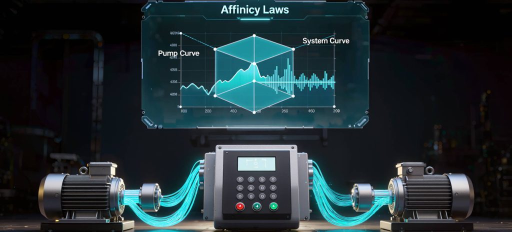
The affinity laws can provide an initial estimate of how flow, head, and power may change with speed under suitable similarity conditions. They do not predict the complete installed result by themselves. The system curve still includes static head, friction, valves, equipment, parallel paths, and changing process pressure.

In a friction-dominated system, speed reduction may move the operating point in a way that resembles a simple affinity-law estimate. In a high-static-head system, the static component does not fall with speed in the same way, so the flow and power response can be very different. The U.S. Department of Energy variable-speed pumping guide explains why the pump/system intersection matters. Do not use a cube-law calculation to promise a universal energy saving.

Plot the pump curves at the proposed speeds against the system curve, then check power, NPSH, minimum flow, control stability, and motor limits at the actual intersections.

Pitfall 2: Treating the speed command as the allowed speed envelope

The VFD command is an input, not proof that the pump can operate safely at that speed. Build an approved envelope using the evidence in the table below.

Limit Evidence to verify
Minimum pump flow Manufacturer/project minimum continuous stable flow, process requirement and recirculation protection
Required process head System curve, pressure boundary, control objective and low-speed intersection
NPSH NPSHa at the real suction condition versus NPSHr over the proposed range
Motor cooling Motor type, fan arrangement, thermal model, load, ambient and low-speed duty
Maximum shaft/pump speed Manufacturer limit, impeller stress, power, pressure, bearings and coupling
Seal and flush Seal chamber pressure, flush/barrier flow, temperature, speed and process compatibility
Vibration/resonance Startup and run-up data, prohibited bands, structure and coupling response
Control sensor Location, range, calibration, response, alarm and loss-of-signal behavior

Use the manufacturer’s limits and project requirements as the controlling basis. A generic minimum-frequency setting is not a universal pump rule.

Pitfall 3: Low-speed operation that loses head or minimum flow

At low speed, the pump may not develop the head required by the process. The control valve may open fully without restoring the required pressure, or the pump may remain at a low-flow condition with internal recirculation. Minimum flow protection may need a dedicated bypass, a control strategy, or a different operating sequence.

Check the low-speed pump/system intersection, suction condition, process pressure, temperature, minimum stable flow, seal flush, lubrication, and motor cooling. The correct minimum speed is project- and equipment-specific.

Pitfall 4: High-speed operation that exceeds load or pressure limits

High speed can increase head, power, pressure, hydraulic force, vibration, and shaft or seal demand. Motor current and VFD output are not the only checks. Verify the pump, impeller, shaft, bearings, coupling, casing, seal chamber, discharge system, relief path, and driver against the approved limit.

If an impeller trim, replacement wet end, or different fluid is introduced, repeat the review. The pump system fundamentals guide explains curve and operating-point relationships that should be used before the drive settings are released.

Pitfall 5: Ignoring resonance and prohibited speed bands

A pump train can pass through a structural or rotating resonance during acceleration, deceleration, or steady operation. The response may show up as a narrow vibration peak, coupling wear, seal leakage, bearing heat, or unstable control. Do not solve a resonance by simply increasing or decreasing a limit without identifying the band and the evidence.

Record run-up and coast-down behavior where appropriate, identify prohibited speed bands, and confirm the drive’s skip-frequency and acceleration/deceleration settings. Check the foundation, base, pipe strain, coupling, alignment, and rotating assembly if the response is not explained by the hydraulic duty.

Pitfall 6: Commissioning without a measurement matrix

Commissioning should use representative points across the approved speed range, not a fixed 25/50/75/100% recipe that may not match the process. Define the points with the responsible engineer and record stable conditions.

Record at each point Purpose
Actual speed or frequency Links the reading to the applicable pump curve
Flow and process variable Checks the duty and control response
Suction and discharge pressure Calculates developed head and supports NPSH review
Motor current and input power Checks driver load and trend
Vibration and bearing temperature Identifies unstable or damaging operating regions
Valve, bypass and alarm state Shows how the system is actually achieving duty
Liquid temperature and process condition Preserves the fluid and demand basis

Record instrument IDs and units, allow stabilization, and note any point that cannot be held. Compare the result with the approved pump curve, system curve, motor data, limits, and acceptance criteria.

Pitfall 7: Failing to define bypass and fail-safe behavior

Define what happens when the pressure, flow, level, or temperature sensor fails; when the VFD faults; when the bypass is selected; when power returns; and when the pump must maintain minimum flow. The safe state may be different for a cooling loop, chemical transfer system, boiler feed service, or hazardous process.

  • Alarm and trip setpoints, ownership, and reset behavior.
  • Manual and automatic bypass logic, including maximum allowed speed in bypass.
  • Minimum-flow protection during startup, shutdown, and loss of demand.
  • Restart, permissive, interlock, and communication-loss behavior.
  • Pressure relief and downstream equipment limits.

When VFD is the wrong fix

A drive is not a substitute for correcting a blocked suction line, wrong impeller, poor alignment, pipe strain, a changed process duty, inadequate NPSHa, a failed seal-support system, or a pump that is fundamentally mismatched to the required head and flow. Use the VFD decision framework for the “should variable speed be used?” question. Use this article after a VFD is being considered or installed to control execution risk.

For energy or operating-point calculations, the pump calculators provide a transparent screening route. For NPSH, compare the actual suction conditions with the NPSHa vs NPSHr guide. If the VFD is part of a broader project, connect it to the pump system optimization workflow.

Need a VFD speed envelope checked before commissioning?

Send the pump curve, system curve or duty data, motor details, speed range, minimum-flow requirement, suction conditions, seal/flush arrangement, control narrative, and any vibration or resonance evidence. ANSI Pumps Pro can help organize the open technical checks.

Request a VFD application review

FAQ

Does a VFD always save energy on a centrifugal pump?

No. The result depends on the system curve, static head, demand profile, control method, pump efficiency, motor and drive losses, operating hours, and actual operating point.

What is the minimum speed for an ANSI centrifugal pump?

There is no universal minimum speed. It must be established from minimum flow, required head, NPSH, motor cooling, seal/flush, lubrication, vibration, control, and manufacturer or project limits.

Can affinity laws predict VFD pump savings exactly?

No. They are useful approximations under suitable conditions, but static head and the actual pump/system curve intersection can materially change the result.

What should be recorded during VFD pump commissioning?

Record actual speed, flow, suction and discharge pressure, motor current or power, vibration, bearing temperature, process variable, valve/bypass state, alarms, liquid condition, and instrument basis at representative approved points.

What happens if a VFD sensor fails?

The control narrative should define alarms, trips, fallback or bypass behavior, minimum-flow protection, restart permissives, and the safe state for the specific process.

Have a pump, part number or drawing to review?

Send the installed model, operating duty and available evidence. We will identify the dimensions, materials and interfaces that must be confirmed before quotation.

Request Engineering Review
Quick Quote