
Mark 3 Pump Specifications
Product Details
| Application | Chemical processing, petrochemical refining, corrosive chemical transfer, pulp & paper mill liquors, reverse vane impeller applications, high-temperature services, MRO replacement programs, EPC project procurement |
| Flow Rate | Up to 7,500 GPM (1,703 m3/h) |
| Head Range | Up to 990 ft (302 m) |
| Temperature | -73 degrees C to 370 degrees C (-100 degrees F to 700 degrees F) |
| Materials | CF8M (316SS), CD4MCuN (Duplex), CN7M (Alloy 20), WCB (Carbon Steel), Hastelloy B, Hastelloy C-276, Nickel 200, Titanium Grade Pd7B, Zirconium 702 |
| Pressure Rating | Up to 27 bar (400 PSIG) |
Fast and accurate impeller setting with the industry’s most innovative external impeller adjustment mechanism.
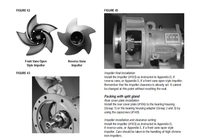
In-shop reverse vane impeller adjustment with the only pump that takes full advantage of the back pull-out design.
BEARING INSTALLATION
FOR POWER END ASSEMBLY (CONT’D)
Both bearings have a slight interference fit which requires that they be pressed on the shaft with an arbor or hydraulic press. A chart giving bearing fits is shown in Figure 35. Even force should be applied to the inner race only. Never press on the outer race, as the force will damage the balls and races. An alternate method of installing bearings is to heat the bearings to 200°F (93°C) in an oven or induction heater.Then place them quickly in position on the shaft.
Packing/gland installation
Install the packing rings (#113) and seal cage halves (#112) into the stuffing box as shown in Figure 16. Always stagger the end gaps 90° to ensure a better seal. To speed installation of each ring, have an assistant turn the pump shaft in one direction. This movement of the shaft will tend to draw the rings into the stuffing box. A split gland (#110) is an assembly of two matched gland halves that are bolted together. Unbolt the gland halves and install the gland halves around the shaft. Bolt the halves together to form a gland assembly. Now, install the gland assembly (#110) using studs (#111) and nuts (#111A).Lightly snug up the gland. Final adjustments must be made after the pump has begun operation.
Popular products
Product Inquiry
Fill out the form below and our team will provide a customized quote for this product.