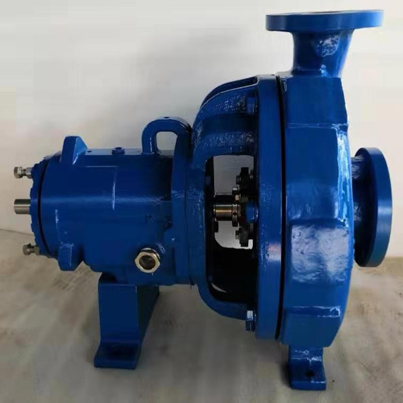
Mark 3 Reverse Impeller Pump
Product Details
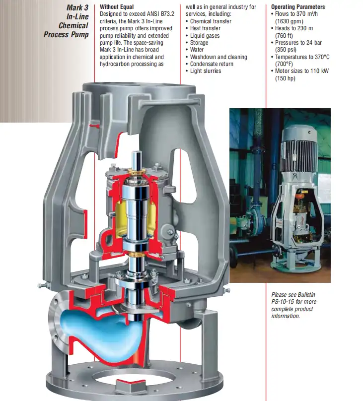
| Application | Chemical processing, petrochemical refining, corrosive chemical transfer, pulp & paper mill liquors, reverse vane impeller applications, high-temperature services, MRO replacement programs, EPC project procurement |
| Flow Rate | Up to 7,500 GPM (1,703 m3/h) |
| Head Range | Up to 990 ft (302 m) |
| Temperature | -73 degrees C to 370 degrees C (-100 degrees F to 700 degrees F) |
| Materials | CF8M (316SS), CD4MCuN (Duplex), CN7M (Alloy 20), WCB (Carbon Steel), Hastelloy B, Hastelloy C-276, Nickel 200, Titanium Grade Pd7B, Zirconium 702 |
| Pressure Rating | Up to 27 bar (400 PSIG) |
ADVANTAGE:
1.Increased reliability and mechanical seal life due to the ideal seal environment created by the SealSentry seal chamber.
2.Ease of maintenance resulting from optimal, predictable seal chamber pressures that are re-established after every impeller setting.
3.Extended mechanical seal and bearing life through robust shaft and bearing designs that also minimize shaft deflection.
4.Fast and accurate impeller setting with the industry’s most innovative external impeller adjustment mechanism.
GENERAL DESCRIPTION OF THE PUMP
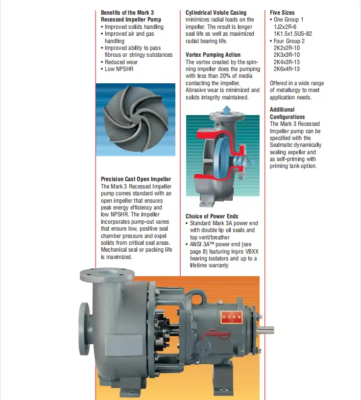
The Recessed Impeller is an open-vane design that has the shroud attached to the rear of the vanes. The impeller is located a distance of two inches or so from the suction face ofthe casing. When the impeller spins, it sets up a vortex within the casing. This swirling liquid is fed from the center via the suction nozzle and exits tangentially from the vortex through thedischarge nozzle.
Very little of any solids that may be contained in the liquid actually touch the impeller. Rather, they are swept up in the swirling motion and conducted in direct fashion to the discharge nozzle. The discharge nozzle is placed at a tangentto the swirling flow so that the fluid flows smoothly out of the pump. Top, center-line discharge is not desirable as the extrabends in the discharge nozzle necessary to locate the flange in the center would disrupt the flow and increase the possibility of wearing out the casing. Except for the impeller and casing, all other parts are identical to the standard Mark III pump.
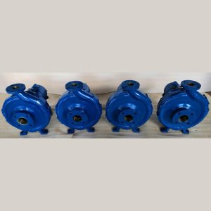
Popular products

Product Inquiry
Fill out the form below and our team will provide a customized quote for this product.