ANSI Pumps Pro · Technical Service Series
There’s a Goulds 3196 sitting in thousands of chemical plants, refineries, and water treatment facilities across North America that’s been running for 20, maybe 30 years. It still moves fluid. It still holds pressure. But the wear rings are past their clearance limit, the impeller shows erosion pitting, and the seal chamber has seen better days.
That pump isn’t ready for the scrap yard. It’s ready for a wet end rebuild — and with the right replacement components, it’ll run another two decades.
This guide walks through the complete rebuild process, component by component. Whether you’re a hands-on millwright or a maintenance planner putting together a scope of work, this is the roadmap. We’ll cover inspection, teardown, replacement decisions, reassembly, and testing — all with an eye toward using 100% interchangeable aftermarket wet end parts that won’t require you to modify a single bolt hole.
Before You Pick Up a Wrench: Pre-Teardown Assessment
Don’t skip this step. A half-hour spent documenting baseline conditions before you tear the pump down will save you hours of head-scratching during reassembly.
Record these measurements with the pump still assembled:
- ✓ Vibration readings at the inboard and outboard bearing housings (horizontal, vertical, axial)
- ✓ Bearing housing temperatures after steady-state operation
- ✓ Suction and discharge pressure at the operating point
- ✓ Visual notes: any external leaks, corrosion patterns, seal flush line condition
- ✓ Shaft axial position reference (measure from a fixed point on the bearing housing to the coupling hub face)
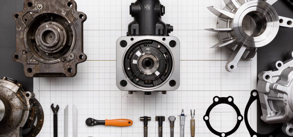
Step 1: Teardown Sequence
Disconnect and Remove the Wet End from the Power End
Unbolt the casing from the adapter (or from the bearing frame, depending on your 3196 vintage). Support the wet end with a sling — even a bare casing is heavier than it looks. Remove the impeller nut (note: it may be a left-hand thread on some configurations; confirm before applying the impact gun).
Remove the impeller using a proper puller, not a pry bar. A gouged shaft shoulder from an impatient teardown becomes your problem during reassembly.
Remove the Stuffing Box Cover and Mechanical Seal
Unbolt the stuffing box cover from the casing. If you’re running a mechanical seal, remove the rotating assembly from the shaft before pulling the stationary seat from the cover. Bag and label the seal parts — you’ll want to reference the seal type and size when ordering a replacement, even if you’re not reusing it.
Extract Wear Rings
The casing wear ring and impeller wear ring are press-fit or tack-welded (depending on vintage). If tack-welded, carefully grind the tack welds without cutting into the parent material. Press or tap out the old rings. Clean the register surfaces thoroughly — any raised metal or residual material here will make the new ring impossible to seat properly.
Inspect the Shaft
With the impeller removed, check the shaft for runout at the impeller fit, the seal fit area, and both bearing journals. Total indicated runout (TIR) should not exceed 0.002″ at any of these locations. If the shaft is worn, scored, or bent, replace it. A new shaft is cheap compared to the collateral damage of a shaft failure under load.
Step 2: The Go / No-Go Decision on Each Component
Not everything needs replacing. Here’s how to decide:
| Component | Replace If… | Likely OK If… |
|---|---|---|
| Impeller | Pitting deeper than 1/16″, vane edge erosion exceeds 1/8″, or wear ring land diameter is below minimum | Surface is smooth, wear ring land is in tolerance, balancing is intact |
| Casing | Wall thickness at any point is below minimum (UT test it), cutwater shows erosion, or gasket surfaces are pitted beyond sealing | UT shows uniform wall thickness, cutwater is clean, gasket faces are smooth |
| Shaft | TIR exceeds 0.002″ at any journal, or visible scoring/fretting at bearing or seal fit surfaces | Shaft runs true, surfaces are clean and smooth |
| Wear Rings | Always replace. These are consumable by design. Running clearance exceeding OEM spec = lost efficiency and vibration. | — |
| Stuffing Box Cover | Seal chamber bore is corroded or galled, or gasket face is deeply pitted | Bore is clean and smooth, gasket face is flat |
| Gaskets & Hardware | Always replace. Gaskets take a set; fasteners can be stretched or corroded. These are the cheapest parts in the rebuild. Don’t reuse them. | — |
When to Replace the Whole Wet End vs. Individual Components
If two or more of the major hydraulic components (impeller, casing, back cover) need replacement, it’s usually more cost-effective and technically cleaner to order a complete wet end kit. You get components machined in the same batch, verified as a matched set, and you avoid the finger-pointing that happens when a new impeller doesn’t quite fit an old casing. The price for a complete kit is typically less than the sum of individual parts ordered separately.
Step 3: Parts Ordering — What to Specify
When you’re ordering aftermarket replacement parts for a Goulds 3196 rebuild, the more information you provide upfront, the smoother the process. Here’s what your supplier needs:
- Pump model and frame size — e.g., Goulds 3196, STX, 3×4-13
- Serial number (if the tag is still legible)
- Material grade required — 316SS, CD4MCuN, Hastelloy C, etc. Don’t guess. If you’re not sure, provide the process fluid composition and temperature and let the supplier’s applications team make a recommendation.
- Seal type and size — the seal chamber dimensions need to match your mechanical seal. If you’re reusing the existing seal, provide the seal manufacturer and model number so the stuffing box cover bore is machined to the correct diameter.
- Any known deviations from standard — previous modifications, non-standard piping connections, special coatings. Surprises discovered during reassembly are expensive.
Step 4: Reassembly Sequence
Install Wear Rings
Press new wear rings into the casing bore and onto the impeller hub. If the original design called for tack welding, apply three equally spaced tack welds (no more than ⅜” each). Verify running clearance between the casing ring ID and impeller ring OD — this should match the OEM specification, typically 0.010″ to 0.020″ diametral clearance depending on pump size and material.
Mount Impeller on Shaft
Clean the shaft taper or keyway thoroughly. Apply a light coat of anti-seize compound to the shaft taper (if tapered fit). Seat the impeller and torque the impeller nut to specification. Confirm the impeller nut thread direction — some are left-hand. Re-check shaft runout after the impeller is mounted.
Install Stuffing Box Cover and Mechanical Seal
Press the stationary seal seat into the stuffing box cover bore using even pressure (a seal installation tool is worth every penny here). Mount the cover onto the adapter/bearing frame with a new gasket. Slide the rotating seal assembly onto the shaft and set the axial position per the seal manufacturer’s installation dimension. Don’t guess at this — measure it. An incorrectly positioned seal cartridge will either leak immediately or fail prematurely.
Install Casing and Set Impeller Clearance
Mount the casing to the adapter with a new gasket. Torque the casing bolts in a cross pattern to the value specified for your pump size. Then set the impeller axial clearance — this is the front clearance between the impeller and casing. Most Goulds 3196 models use an external adjusting screw on the bearing housing. Rotate the shaft by hand while adjusting to confirm there’s no rub. The final clearance should match the OEM specification for your frame size.
Final Alignment Check
With the pump fully assembled, check the coupling alignment between the pump and motor shafts. The wet end rebuild shouldn’t have changed the alignment — the casing foot height on a properly manufactured replacement casing matches the OEM dimension — but you check it anyway. It takes ten minutes and it prevents bearing failures that take days to fix.
Step 5: Pre-Startup Checks
- ✓ Rotate the shaft by hand — it should turn freely with no rub, no catch, no grinding
- ✓ Confirm seal flush/support system is connected and operational (if applicable)
- ✓ Check bearing housing oil level (power end side)
- ✓ Vent the casing — open the vent until liquid comes out, then close
- ✓ Bump the motor to confirm rotation direction before going to full speed
How Long Should a Rebuild Take?
With parts on hand and a two-person crew:
| Rebuild Scope | Typical Shop Hours | Notes |
|---|---|---|
| Wear rings + gaskets + seal only | 4–6 hours | No heavy rigging required; can often be done in place |
| Impeller + wear rings + seal + shaft | 8–12 hours | Requires impeller puller, seal installation tool |
| Complete wet end (casing + impeller + cover + shaft) | 12–16 hours | Requires rigging for casing removal/installation; alignment check essential |
The real timeline variable isn’t the labor — it’s parts availability. A crew ready to work with no parts on the shelf is a crew waiting. That’s been the core driver behind the shift toward shorter-lead-time aftermarket wet end components. When the rebuild parts arrive in 5 weeks instead of 16, the entire maintenance schedule compresses.
Planning a 3196 Rebuild? Let’s Get the Parts Lined Up
Send us your pump tag info and a scope of what you’re planning to replace. We’ll put together a quotation with lead times and a documentation package — MTRs, dimensional reports, hydrostatic certs — so your rebuild file is complete before the parts even arrive.