When to Replace: Recognizing Mechanical Seal Failure
A mechanical seal in a Durco Mark III ANSI process pump does not fail without warning signs. Recognizing these indicators early — and acting on them promptly — is the difference between a planned $500 seal replacement performed during a scheduled maintenance window and a $15,000+ emergency repair involving a destroyed bearing frame, a scored shaft, and three days of lost production.
Key failure indicators that demand immediate pump shutdown and seal replacement:
- Continuous visible leakage from the seal gland weep hole or drain connection. A properly functioning mechanical seal should exhibit no visible liquid leakage. A slight vapor emission (barely perceptible) may be acceptable for certain light hydrocarbon services, but any visible drip or stream requires action.
- Leakage rate exceeding 1-2 drops per minute — for reference, a single drop per second equates to approximately 1,500 gallons per year. In hazardous chemical service, this is a process safety incident, not a maintenance inconvenience.
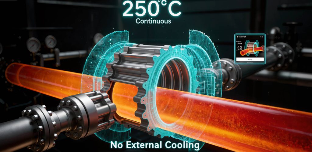
- Increased seal chamber temperature — measured at the gland or seal chamber exterior with a contact thermometer or infrared camera. A temperature rise of 20°C (36°F) or more above the normal operating baseline, at constant process conditions, indicates excessive seal face friction — typically from face distress, loss of lubrication, or incorrect installation compression.
- Visible vapor, fuming, or crystallization at the atmospheric side of the seal — these indicate that process fluid is crossing the seal faces and flashing or reacting on the atmospheric side.
- Bearing housing oil contamination — process fluid that has migrated past the seal, along the shaft, and through the inboard bearing isolator into the bearing oil. Milky oil is a late-stage symptom; by the time this is apparent, both the seal and the inboard bearing may already be compromised.
Critical safety note: Mechanical seal leakage in chemical service poses risks beyond equipment damage — personnel exposure to toxic or corrosive fluids, fire risk from flammable leakage, and environmental release. All seal replacement work described below assumes that the pump has been properly isolated, de-energized, drained, flushed, and declared safe for maintenance by a qualified authorized person in accordance with the facility’s Lockout/Tagout (LOTO) and line break procedures. Never attempt to service a chemical pump without complete energy isolation and verification of zero hazardous material presence.
Step-by-Step Mechanical Seal Replacement Procedure
Step 1: Safety Isolation (LOTO) and Preparation
- Execute the site-specific Lockout/Tagout procedure for the pump driver (electric motor, steam turbine, or engine). Verify zero energy state by attempting to start the driver from its local control station.
- Close the suction and discharge isolation valves. Verify closure by observing the valve stem position indicator and by attempting to move the valve handwheel.
- If the pump casing is equipped with a drain connection, slowly and carefully open the drain valve to empty the casing of residual process fluid into an appropriate containment vessel. Wear full chemical PPE appropriate for the specific process fluid — at minimum, chemical-resistant gloves, face shield, and chemical apron.
- If the pump handles a fluid that can crystallize, polymerize, or form solid deposits upon cooling or exposure to air, flush the casing with an appropriate solvent or neutralizing solution before proceeding. Solidified product inside the seal chamber can damage new seal faces upon restart.
- Disconnect any auxiliary piping connected to the seal gland — API Plan flush lines, quench lines, vent/drain tubing, and seal environmental control piping. Cap or plug all open connections to prevent contamination.
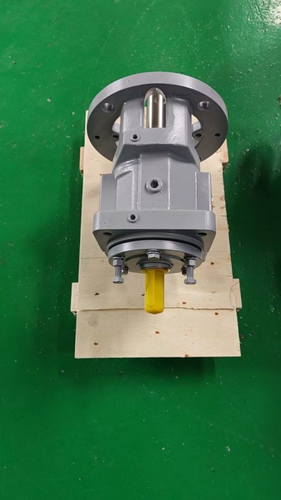
Step 2: Remove the Back Pull-Out Assembly
The Durco Mark III, like all ASME B73.1 pumps, is designed as a back pull-out (BPO) pump. This means the entire rotating assembly — impeller, shaft, bearings, bearing housing, adapter, and seal chamber cover — can be removed from the casing as a single unit without disturbing the pump casing, suction/discharge piping, or motor. This is the single greatest time-saver in ANSI pump maintenance.
⚠️ Quality & Compliance Assurance
All pumps and components from ANSI Pumps Pro are manufactured to ASME B73.1 dimensional specifications. Each shipment includes certified Material Test Reports (MTRs), CMM dimensional inspection reports, and hydrostatic test certificates (1.5× MAWP). 100% dimensional interchangeability guaranteed. Full material traceability from heat number to your receiving dock.
- Remove the spacer coupling between the pump and motor shafts. The spacer section is designed to be removed without moving either the pump or the motor — simply unbolt the spacer from both coupling hubs and lift it out. Do NOT disturb the coupling hubs on either shaft, as this preserves the shaft alignment.
- Remove the casing bolts that secure the adapter (also called the frame adapter or bearing frame adapter) to the pump casing.
- Using the jacking bolt holes provided in the adapter flange (a standard ASME B73.1 feature), thread in bolts to break the adapter-to-casing joint. The entire back pull-out assembly — bearing housing, shaft, bearings, impeller, adapter, and seal chamber cover — will slide rearward as a single unit.
- Support the assembly with an appropriate lifting device (overhead crane, mobile gantry, or forklift with lifting strap) rated for the assembly weight. For Group 2 (MTX/MTi) and Group 3 (XLT-X/XL17) frame sizes, the complete BPO assembly can weigh 300-800+ lbs.
- Move the BPO assembly to a clean, well-lit work area with adequate bench space for disassembly.
Step 3: Disassemble the Wet End to Access the Seal
- Remove the impeller. The Durco Mark III impeller is threaded onto the shaft. Determine the thread direction before applying force — most Mark III impellers use a right-hand thread (standard rotation direction viewed from the coupling end), but confirm from the pump documentation. Use the correct sized wrench or spanner on the impeller flats; never apply pipe wrenches to impeller vanes, as this will damage the hydraulic surfaces. If the impeller is seized due to corrosion or product solidification, apply penetrating oil and allow to soak; if heat is necessary, use only indirect, controlled heating (never a torch directly on the impeller casting).
- Once the impeller is removed, slide the seal chamber cover / rear cover off the shaft. This exposes the mechanical seal rotary unit and the seal chamber bore. The rear cover may have a registered fit with the adapter; if it is stuck, use the jacking bolt provisions to break it free evenly — do not pry at one point, as this can distort the register.
- Remove the old mechanical seal rotary unit by loosening the set screws that secure it to the shaft sleeve (or directly to the shaft, depending on seal design). Slide the rotary unit off the shaft. If the seal is a cartridge (pre-assembled) type, the entire seal assembly — rotary unit, stationary seat, gland plate, and sleeve — may come off as one piece once the gland bolts are removed.
- Remove the stationary seat from the seal chamber bore (or gland plate, depending on seal configuration). The stationary seat is often a press-fit in its housing; use a wooden or plastic dowel to tap it out evenly from the rear. If the stationary seat O-ring or gasket has hardened from heat exposure, it may require careful prying — again, protect the seal chamber bore surface from scratches.
Step 4: Inspect and Prepare the Seal Chamber
The condition of the seal chamber bore and the rear cover face directly influence the new seal’s reliability. Take time to prepare these surfaces properly — the few extra minutes spent here will pay back many times over in extended seal life.
- Clean the seal chamber bore thoroughly. Remove all deposits, scale, carbonized product, and old gasket material. Use a non-metallic scraper (plastic or brass) to avoid scratching the bore surface. For the Durco Mark III’s standard bore or taper bore (large bore) seal chamber, pay particular attention to the stationary seat counterbore — the register surface where the stationary seat O-ring seals must be clean, smooth, and free of pits or scratches.
- Inspect for corrosion or erosion damage. Look for pitting at the O-ring seating area, erosion from flashing or cavitation damage, and cracks — particularly at section transitions or near bolt holes. Any defect that could compromise the stationary seat O-ring seal requires repair or replacement of the seal chamber cover.
- Verify the seal chamber face flatness where the gland plate mates. Place a straightedge across the face and check with feeler gauges. Out-of-flatness exceeding 0.002 inches over the gland diameter should be corrected by light lapping or machining.
- Inspect the shaft sleeve (if the seal mounts on a sleeve). Refer to the shaft sleeve inspection criteria in our separate Goulds 3196 troubleshooting guide — the same inspection standards (OD wear limit 0.002 inches, surface finish Ra 0.8 μm max, TIR 0.002 inches max) apply equally to the Durco Mark III.
Step 5: Install the New Mechanical Seal
For a component seal (separate rotary and stationary units):
- Lubricate the stationary seat O-ring with a thin film of compatible assembly lubricant — the seal manufacturer will specify the appropriate lubricant (often silicone-based for EPDM O-rings, or a specific assembly paste). Never use petroleum grease on EPDM or Viton elastomers.
- Press the stationary seat into the seal chamber bore (or into the gland, depending on seal design) squarely and evenly. Use an installation tool (often provided with the seal) or a clean, flat pressing block that contacts the entire seat face simultaneously. Do not press on one edge — tilting the seat will damage the O-ring and cause immediate leakage. The seat must bottom fully and squarely in its counterbore.
- Slide the rotary unit onto the shaft (or shaft sleeve), again using only the recommended assembly lubricant on the O-ring / bellows ID. Do not tighten the set screws yet.
- Position the gland plate and tighten the gland bolts evenly in a cross pattern to the specified torque. Uneven gland tightening is a common cause of stationary seat distortion and immediate seal leakage.
- Set the correct spring compression according to the seal manufacturer’s installation dimension — typically measured from the gland face to a reference point on the rotary unit. This is the most critical dimension in the entire seal installation. Under-compression causes leakage; over-compression causes excessive heat generation and rapid face wear. Use the manufacturer’s setting fixture if provided, or measure with a depth micrometer.
- Once the correct spring compression is verified, tighten the set screws to the seal manufacturer’s specified torque, using a calibrated torque wrench. Tighten in stages (50%, then 100% of target torque) and in sequence if multiple set screws are used.
For a cartridge seal (pre-assembled unit):
- Verify that the cartridge setting tabs / clips are in place and secure. These tabs hold the seal at the correct working length during installation.
- Slide the complete cartridge assembly over the shaft and into the seal chamber bore.
- Tighten the gland bolts evenly in a cross pattern.
- Tighten the shaft locking device (typically a clamp ring or set of radial set screws) to the specified torque.
- Remove the setting tabs / clips and store them — they will be needed for the next seal replacement. The shaft should now rotate freely without the seal faces binding.
Step 6: Reassemble and Set Impeller Clearance
- Reinstall the seal chamber cover / rear cover onto the adapter register. Ensure the gasket or O-ring is properly seated.
- Thread the impeller onto the shaft to the correct position. Use anti-seize compound on the shaft threads if the pump handles a corrosive fluid.
- Set the impeller clearance. On the Durco Mark III, this is done at the rear cover using the external jacking bolts, as described in detail in our separate article on impeller adjustment. The critical point: because the Mark III adjustment is independent of the mechanical seal, the seal setting is not disturbed by the clearance adjustment — unlike the Goulds 3196 where the seal must be re-verified after adjustment.
- Rotate the shaft by hand to confirm free rotation without rubbing or binding at any point in a full 360° revolution.
Step 7: Reinstall the Back Pull-Out Assembly and Align
- Clean the casing register and adapter register surfaces. Install a new casing gasket — never reuse a casing gasket on a chemical pump. A leaking casing gasket creates a process safety hazard and can spray corrosive fluid onto personnel and nearby equipment.
- Slide the complete back pull-out assembly into the casing. Guide it in straight to avoid damaging the casing gasket. Engage the register fit fully.
- Install and tighten the casing bolts evenly in a cross pattern to the torque specified in the pump manual. Uneven bolt tightening can distort the casing and cause internal rubbing.
- Reinstall the spacer coupling. Re-check the shaft alignment — even though the pump and motor were not moved, the back pull-out assembly may sit slightly differently on the baseplate after reassembly. Final alignment should be within 0.002 inches TIR for both angular and parallel misalignment at the coupling.
- Reconnect auxiliary piping, remove LOTO devices, and prepare for restart per site startup procedures.
Post-Installation Commissioning Checklist
Before returning the pump to service, verify:
- ✓ All casing bolts, gland bolts, coupling bolts, and auxiliary connections are properly torqued
- ✓ Shaft rotates freely by hand — no rubbing, binding, or intermittent drag
- ✓ Bearing housing oil level is correct — at the center of the lowermost bearing ball
- ✓ Seal environmental controls (API Plans) are connected, valves are in the correct position, and flush fluid is flowing if applicable
- ✓ Pump casing is properly vented and primed before starting the driver
- ✓ On initial startup, observe the seal area closely for the first 15 minutes of operation for any sign of leakage, abnormal noise, or smoke/vapor
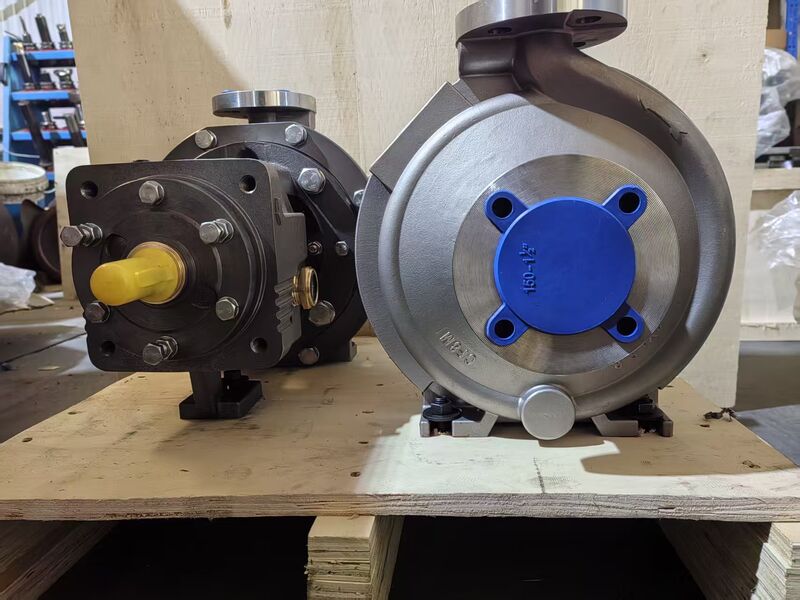
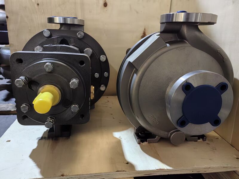
Durco Mark III Seal System Components from ansipumpspro.com
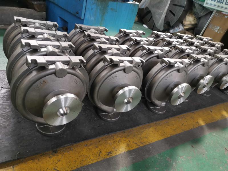
A successful mechanical seal replacement depends not only on the skill of the technician but also on the dimensional accuracy and material quality of every component in the seal system. At ansipumpspro.com, we support Durco Mark III pump operators with a complete range of seal system replacement components:
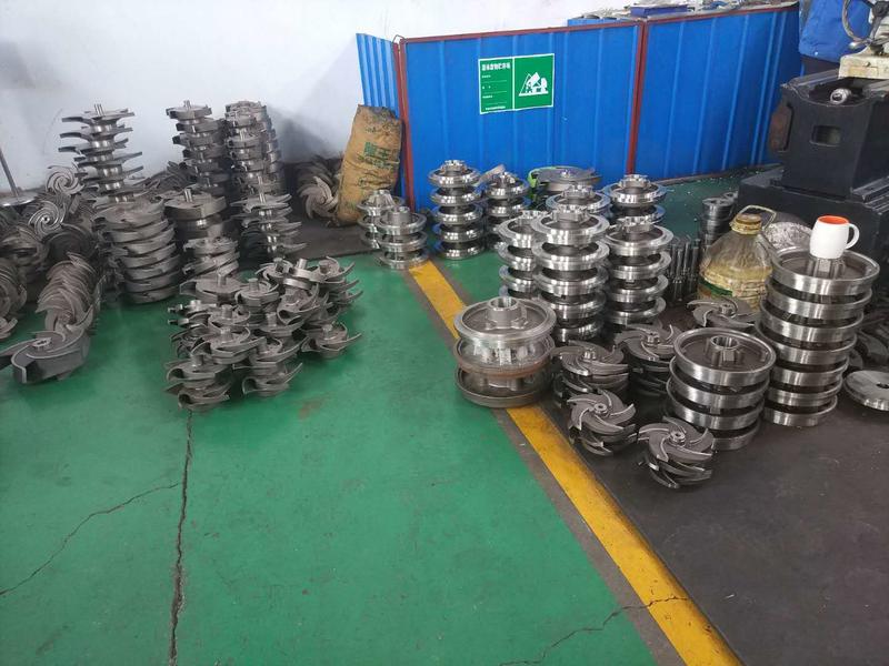
- Seal chambers / stuffing box covers — available in both Standard Bore and Taper Bore (Large Bore) configurations, investment cast in 316SS, Alloy 20, Hastelloy C-276, and CD4MCu. Bore dimensions, gland stud locations, and register fits match OEM specifications exactly.
- Shaft sleeves — in the material grades and hard-coating options detailed in our shaft sleeve troubleshooting guide. Proper sleeve OD and surface finish are critical for seal O-ring sealing.
- Casing gaskets, O-ring kits, and seal chamber gaskets — in the elastomer or composite material appropriate for the specific process chemistry and temperature.
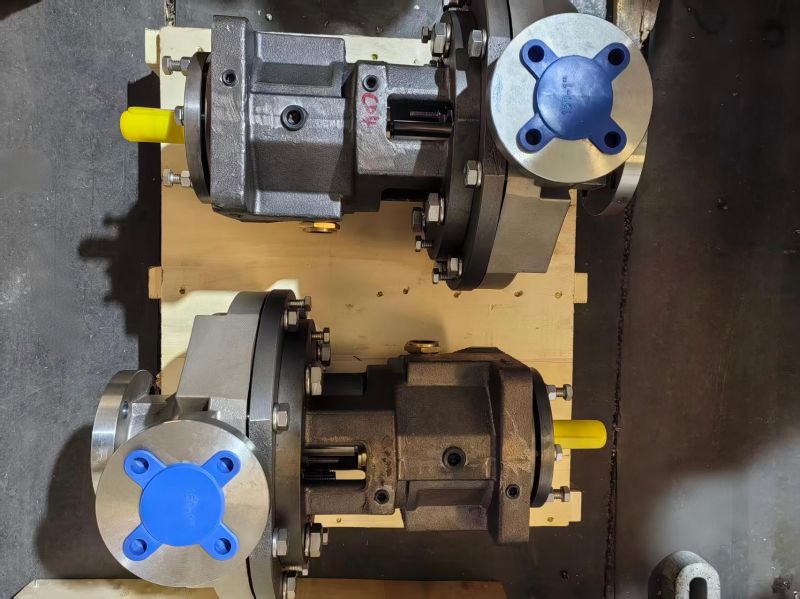
- Complete wet end assemblies — casing, impeller, seal chamber, shaft sleeve, and all gaskets, pre-assembled and ready for bolt-on installation. Ideal for minimizing downtime during planned turnarounds.
- Mechanical seals — we can supply or cross-reference the correct seal for your Mark III pump based on the pump model, seal chamber type (standard bore or taper bore), shaft/sleeve diameter, and process conditions.
All components are manufactured in accordance with ASME B73.1 dimensional requirements and are 100% interchangeable with the corresponding Flowserve Durco Mark III OEM parts. No modifications to your pump, piping, or seal auxiliary systems are required.
For technical assistance with mechanical seal selection, to cross-reference your Durco Mark III part numbers, or to request a quotation for seal system components, contact our service team at ansipumpspro.com/contact.
📋 Quick RFQ — No Registration Required
🔗 Related Reading
Quick Reference: Common Mechanical Seal Failure Patterns
| Symptom | Probable Cause | Immediate Action |
|---|---|---|
| Continuous drip from gland | Seal face wear or damage; O-ring degradation | Check for shaft runout >0.002″ TIR; verify flush line flow |
| Intermittent spray at startup | Seal faces not closing; dynamic O-ring hanging | Inspect shaft sleeve for fretting; replace O-ring |
| Black dust around seal | Carbon face running dry; insufficient flush | Verify Plan 11 flush; check for vapor in seal chamber |
| Leak stops when pump stops | Dynamic seal failure; faces opening under vibration | Check coupling alignment; balance impeller to ISO G6.3 |
Pro tip: Before removing any seal, measure and record the sleeve position relative to the seal housing. This reference simplifies reassembly and avoids the most common post-replacement alignment error.