Durco Mark III vs Goulds 3196 — Parts Interchangeability Guide

When maintaining ANSI B73.1 process pumps, plant engineers and procurement teams frequently face a critical question: Can Durco Mark III parts be used in Goulds 3196 pumps, and vice versa? The answer is nuanced — some components interchange directly, while others require understanding of the fundamental design differences between these two industry-standard pump platforms.

This guide provides a comprehensive, part-by-part interchangeability analysis based on 15+ years of reverse-engineering both pump families. As an independent aftermarket manufacturer producing replacement parts for both Goulds 3196 (G196 Series) and Durco Mark III (D Mark III Series), we have deep insight into where the two designs converge and where they diverge.

The Foundation: ASME B73.1 Dimensional Standard

Both Goulds 3196 and Durco Mark III pumps are manufactured to ANSI/ASME B73.1 — the governing standard for horizontal end-suction centrifugal pumps in chemical process service. This means:

  • Mounting footprint is identical — baseplate bolt patterns match, so a Durco Mark III pump can be dropped directly onto a Goulds 3196 base without modification.
  • Nozzle locations are standardized — suction and discharge flange positions and dimensions are consistent across both brands within the same frame size.
  • Shaft centerline height — the critical dimension for coupling alignment — is the same for equivalent frame sizes (STX/Group I, MTX-LTX/Group II, XLTX/Group III).
  • Overall pump dimensions (CP, D, X, E, F, Y, H, U values) match within tolerance, enabling direct whole-pump swap-outs.

Bottom line: You can replace an entire Goulds 3196 with a Durco Mark III equivalent (or our G196/D Mark III aftermarket pumps) without touching piping, baseplates, or motor mounts.

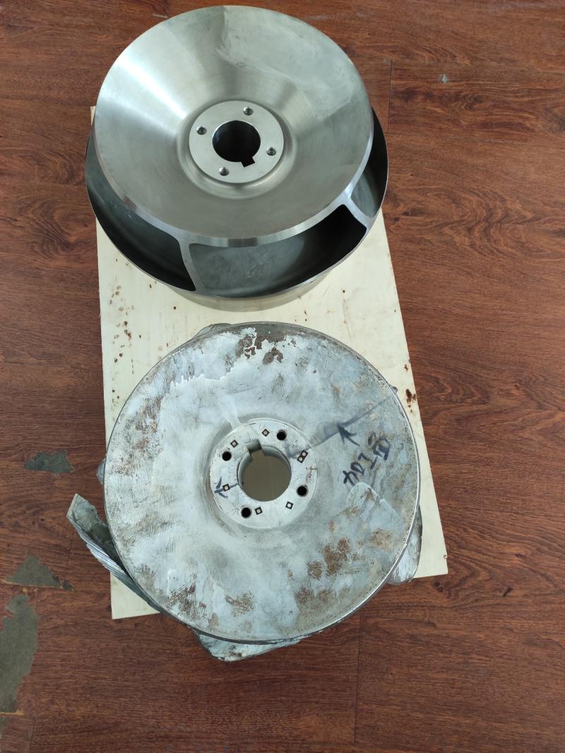
Key Design Difference: Open Impeller vs. Reverse Vane Impeller

Before diving into part-level interchangeability, it’s essential to understand the single biggest technical difference between these two pump families:

FeatureGoulds 3196 (G196 Series)Durco Mark III (D Mark III)
Impeller TypeOpen impellerReverse vane (semi-open) impeller
Front Clearance AdjustmentExternal adjustment against front casingExternal adjustment against rear cover plate
Seal Chamber PressureStandard — front wear ring controls leakageReduced — rear pump-out vanes lower seal chamber pressure
Thrust LoadHigher axial thrust (open face)Lower axial thrust (balanced by rear vanes)
Mechanical Seal LifeStandardExtended — lower seal chamber pressure reduces seal face loading
Wear Ring LocationFront casing wear ringNo front wear ring — rear cover plate serves as wear surface

This means: You cannot simply thread a Durco impeller onto a Goulds shaft, or vice versa. The entire wet-end assembly (impeller, cover, casing) is designed as an interdependent system. However, individual power-end components are far more interchangeable.

Part-by-Part Interchangeability Matrix

The following table shows interchangeability at the component level. Use this as a quick reference when sourcing replacement parts for either pump platform.

ComponentGoulds 3196 POSDurco Mark III POSDirect Interchange?Notes
Casing (Volute)100100⚠️ Wet-end onlySame nozzle dimensions per ANSI B73.1, but internal volute profile differs. Replace as a complete wet-end assembly.
Impeller101104❌ Not directlyOpen vs. reverse vane design. Shaft taper/fit may differ. Replace impeller + cover + casing as a set for cross-brand swaps.
Shaft122107⚠️ Check fitSame SAE 4140 or 316SS material. Shaft diameters at bearing seats typically match within same frame group, but impeller-end taper, keyway, and sleeve fit must be verified.
Shaft Sleeve126201B (Hook Sleeve)⚠️ Check dimensionsBoth use 316SS. Length and OD match within same group, but hook sleeve design on Durco requires matching gland.
Stuffing Box Cover / Seal Chamber184 / 184M108 (Rear Cover)❌ Different designGoulds uses front cover with wear ring; Durco uses rear cover plate. Not interchangeable.
Bearing Housing228129⚠️ Frame-levelBolt pattern and shaft centerline match within same frame group. Verify bearing bore diameters.
Bearing Frame / Frame Adapter108109A⚠️ Assembly-levelMounting bolt pattern often matches. Replace with bearings as a complete assembly.
Thrust Bearing112130 / 131✅ Often sameBoth use SKF or equivalent angular contact / deep groove bearings. Standard bearing numbers cross-reference directly.
Gland (Packing)250112⚠️ Check fitGland bolt PCD may vary. Verify stud spacing before ordering.
Gasket — Casing351105❌ DifferentCasing gasket profiles are unique to each brand’s volute design.
Oil Seals (Inboard/Outboard)332A / 333A125 / 136✅ Same functionLabyrinth oil seals (INPRO VBXX or equal) — cross-reference by shaft diameter and housing bore.
Oil Sight Glass319153 / 245✅ Standard partGeneric component. Interchangeable if thread size matches.

Frame Group Correspondence: Which Pump Sizes Match?

Use this cross-reference table to find the equivalent pump size across both brands. Pumps in the same row share identical mounting dimensions (baseplate, nozzle locations, shaft centerline).

Goulds 3196 FrameDurco Mark III GroupCommon Pump SizesMax ImpellerShaft Centerline
STXGroup I (1K)1×1.5-6, 1.5×3-6, 2×3-6, 1×1.5-8, 1.5×3-8, 2×3-8, 3×4-86″–8″17.5″ (445 mm)
MTX / LTXGroup II (2K)1×2-10, 1.5×3-10, 2×3-10, 3×4-10, 4×6-10, 1.5×3-13, 2×3-13, 3×4-13, 4×6-13, 6×8-13, 8×10-1310″–13″23.5″ (597 mm)
XLTXGroup III (3K)6×8-15, 8×10-15, 3×6-14, 3×6-16, 4×6-16, 6×8-16, 8×10-16, 10×12-16, 8×10-1715″–17″33.875″ (860 mm)

Practical Guidelines for Cross-Brand Parts Sourcing

✅ What You CAN Safely Do

  • Complete pump replacement: Our G196 and D Mark III pumps are 100% dimensionally interchangeable with both Goulds 3196 and Durco Mark III respectively — same footprint, no piping changes.
  • Complete wet-end assembly: Swap a full wet-end (casing + impeller + cover) between brands if within the same frame group. Dimensions match at the adapter interface.
  • Power-end components: Bearings, oil seals, bearing housings, shafts, and sleeves within the same frame group can often interchange after dimensional verification.
  • Gaskets & O-rings by dimension: Generic gaskets and O-rings in standard materials (Aramid, PTFE, FKM, NBR) interchange freely when dimensions match.

❌ What You Should NOT Do

  • Never mix impeller types across brands — a Goulds open impeller won’t function correctly in a Durco reverse-vane casing, and vice versa.
  • Never mix casing covers across brands — the cover-to-casing interface geometry is brand-specific.
  • Never assume shaft interchangeability without verification — impeller-end tapers, keyway dimensions, and sleeve-land diameters differ between the two platforms.

How We Ensure True Interchangeability

At ANSI Pumps Pro (JINAN YINGSIMAN MACHINERY CO., LTD.), every replacement part we manufacture is validated against OEM dimensional databases accumulated over 15+ years. Our process includes:

  • Reverse engineering from OEM samples — we maintain complete drawing libraries for both Goulds 3196 and Durco Mark III across all frame sizes.
  • CMM (Coordinate Measuring Machine) inspection — every critical dimension verified to OEM tolerances before the part leaves our facility.
  • Dynamic balance testing — all impellers balanced to ISO 1940 G6.3 or better.
  • 100% fit-testing — components are trial-assembled on reference fixtures to guarantee field interchangeability.
  • Full MTR (Material Test Report) EN 10204 3.1 — traceable chemical and mechanical properties for every heat of material.

Need help identifying the correct replacement part? Contact our engineering team with your pump model, serial number, or OEM part number — we’ll provide a cross-reference within 24 hours.

Quick Cross-Reference: OEM Part Numbers

Common OEM casing part numbers by pump size, with our equivalent replacement reference numbers:

Pump SizeGoulds 3196 OEM Casing #Durco Mark III OEM Casing #Our Equivalent Ref.
1×1.5-6 (STX / Group I)GAB100 / 104554DKA100 / DY50794AAvailable — inquire
1.5×3-6 (STX / Group I)GAC100 / 104556DKC100 / DY50733AAvailable — inquire
2×3-6 (STX / Group I)GAD100 / 104555DKE100 / BY40035AUAvailable — inquire
3×4-8 (STX / Group I)GAE100 / 104557Available — inquire
1.5×3-8 (MTX / Group I)GAC100 / 104556DAF100 / DY46070AAvailable — inquire
2×3-8 (MTX / Group I)GYB100 / D06628ADAG100 / DY46161AAvailable — inquire
3×4-8 (XLTX / Group I)GAE100 / 104557DYC100 / BY40035AVAvailable — inquire
1×2-10 (LTX / Group II)GAF100 / 24741DAH100 / DY46950AAvailable — inquire
1.5×3-10 (LTX / Group II)GAGG100 / 24745DAJ100 / CY22118AAvailable — inquire
2×3-10 (LTX / Group II)DAN100 / CY22235AAvailable — inquire
3×4-10 (LTX / Group II)GAH100 / 104878DAQ100 / DY47208AAvailable — inquire
4×6-10 (XLTX / Group II)GYC100 / D06638ADYD100 / BY40035AWAvailable — inquire
1.5×3-13 (XLTX / Group II)GAJ100 / 24960DAU100 / CY22344AAvailable — inquire
2×3-13 (XLTX / Group II)GAL100 / 24961DAV100 / DY50172AAvailable — inquire
3×4-13 (XLTX / Group II)GAN100 / 24962DAW100 / DY33074AAvailable — inquire
6×8-13 (XLTX / Group II)GAP100 / D00452A02DNA100 / DY32218AAAvailable — inquire
8×10-15 (XLTX / Group III)GAS100 / 24963DNE100 / DY51013AAvailable — inquire
3×6-16 (Group III)DNB100 / DY48876AAAvailable — inquire
6×8-16 (Group III)GAT100 / D02450ADNF100 / DY30546AAvailable — inquire
8×10-17 (Group III)DNH100 / CY29134AAvailable — inquire

Need full interchangeability data for your specific pump size? Send us your pump nameplate details — we’ll provide a complete cross-reference and quotation within 48 hours.


Disclaimer: Goulds® and 3196 are registered trademarks of ITT Corporation. Durco® and Mark III are registered trademarks of Flowserve Corporation. ANSI Pumps Pro is an independent aftermarket manufacturer. Part numbers are used for cross-reference identification purposes only.

Durco Mark III Impeller Reverse Vane Technology Explained

The Flowserve Durco Mark III process pump is distinguished by one key engineering innovation: the reverse vane impeller. Unlike conventional open or closed impellers, the reverse vane design fundamentally changes how hydraulic forces are managed inside the pump — reducing seal chamber pressure, lowering axial thrust, and extending mechanical seal life. Understanding this technology is essential for maintenance engineers, reliability managers, and anyone sourcing replacement parts for Durco Mark III pumps.

At ANSI Pumps Pro, we have been reverse-engineering and manufacturing Durco Mark III reverse vane impellers for over 15 years. Our aftermarket impellers are cast and machined to micron-level precision, fully inheriting the performance characteristics and reliability advantages of the original OEM design.

What Is a Reverse Vane Impeller?

A conventional open impeller (as used in Goulds 3196) has vanes on the front face only. The radial clearance between the impeller front and the casing is adjusted externally to control internal recirculation and maintain hydraulic efficiency. As the impeller and casing wear, this clearance must be periodically adjusted toward the front (casing side).

A reverse vane impeller (Durco Mark III) adds a set of pump-out vanes on the rear shroud of the impeller. These rear vanes:

  • Actively pump fluid away from the seal chamber — the rotating rear vanes create a centrifugal pumping action that reduces pressure at the mechanical seal faces.
  • Balance axial thrust — by generating a counter-acting pressure on the back side of the impeller, rear vanes partially offset the forward hydraulic thrust, reducing bearing loads.
  • Enable rear-side clearance adjustment — the Durco Mark III is designed to have its impeller clearance adjusted against the rear cover plate (not the front casing), which means the adjustment mechanism is outside the process fluid path.

Reverse Vane vs. Open Impeller — Technical Comparison

Performance FactorOpen Impeller (Goulds 3196)Reverse Vane Impeller (Durco Mark III)Impact
Front clearance adjustmentExternal — adjusts impeller toward front casingExternal — adjusts impeller toward rear cover plateReverse vane: adjustment mechanism is isolated from process fluid, reducing corrosion risk on adjustment threads
Seal chamber pressureNear discharge pressure30–50% lower than discharge pressure (rear vanes pump fluid away from seal)Lower seal face pressure = longer mechanical seal life (2–3× typical MTBPM)
Axial thrustFull forward thrust (unbalanced)Partially balanced by rear vane counter-forceReduced bearing loads = extended bearing life, especially on larger frame sizes
NPSH RequiredStandard (open eye)Comparable to open impellerNo significant difference — reverse vanes do not affect suction performance
Wear characteristicsFront casing and wear ring wearRear cover plate wear (replaceable surface)Reverse vane: wear is on an easily replaceable cover plate, not the expensive casing
EfficiencyStandardComparable (rear vanes add negligible power draw)No efficiency penalty — rear vane pumping work is recovered as pressure
Solids handlingGood (open passages)Good (rear vanes help expel solids from seal area)Reverse vane can be superior in services with suspended solids — rear vanes prevent solids accumulation at seal

How Clearance Adjustment Works in the Durco Mark III

Understanding the clearance adjustment mechanism is critical for proper maintenance. The Durco Mark III uses an external micrometer adjustment that moves the entire bearing housing and shaft assembly relative to the casing:

  1. The shaft and impeller assembly is mounted in the bearing housing, which sits on the bearing housing adapter.
  2. The adjustment bolt (jacking bolt, POS 469B) on the bearing housing moves the entire rotating assembly forward or backward.
  3. Moving the impeller toward the rear cover plate closes the rear clearance gap. This is the opposite direction of conventional open impeller adjustment.
  4. The shim pack (POS 111A) between the adapter and casing is adjusted to set the correct front clearance.
  5. Properly set, the impeller runs with a precise gap on both front and rear faces — typically 0.015″–0.025″ (0.38–0.64 mm) depending on pump size and service temperature.

Critical maintenance note: Because rear clearance is the controlled dimension on a Durco Mark III, the rear cover plate (POS 108) serves as a sacrificial wear surface. This plate should be inspected for wear at every major service interval and replaced when grooving exceeds 1/16″ (1.6 mm).

Three Key Advantages of Reverse Vane Technology

1. Extended Mechanical Seal Life

This is the #1 reason plants choose Durco Mark III pumps for difficult sealing applications. The rear pump-out vanes reduce seal chamber pressure by 30–50% compared to a conventional open impeller. Lower pressure at the seal faces means:

  • Reduced seal face loading → less heat generation → slower wear
  • Lower vapor pressure margin → less risk of flashing at the seal faces
  • Continuous flushing effect → rear vanes circulate fluid away from the seal, preventing stagnant hot spots

Field data from chemical plants shows 2–3× longer MTBPM (Mean Time Between Planned Maintenance) for Durco Mark III pumps vs. equivalent-sized open impeller pumps in the same service.

2. Reduced Axial Thrust and Bearing Load

In a centrifugal pump, the pressure differential across the impeller creates a net forward axial force. In a conventional open impeller, this force is carried entirely by the thrust bearing. The Durco Mark III’s rear vanes generate a counter-acting pressure distribution on the back shroud, partially balancing the axial thrust.

Result: lower thrust bearing loads, reduced bearing temperatures, and extended bearing service intervals — especially significant on larger Group II and Group III frame sizes where thrust loads can exceed 1,000 lbs (4.5 kN).

3. Superior Wear Management

In a conventional open impeller pump, wear occurs between the impeller front face and the casing — meaning the expensive casing must be replaced or re-machined when wear exceeds acceptable limits. In the Durco Mark III reverse vane design, the controlled wear surface is the rear cover plate (POS 108) — a relatively inexpensive, easily replaceable component. This design philosophy significantly reduces long-term maintenance costs.

Our Manufacturing Precision — Micron-Level Accuracy

The performance of a reverse vane impeller depends critically on manufacturing precision. The rear vane height, vane angle, and clearance gap must be held to exact tolerances — deviations as small as 0.002″ (50 microns) can alter seal chamber pressure characteristics and reduce the design benefits.

At ANSI Pumps Pro (JINAN YINGSIMAN MACHINERY CO., LTD.), our aftermarket Durco Mark III impellers are manufactured to the same precision as OEM:

  • Investment casting / lost foam casting — produces near-net-shape impeller castings with excellent surface finish and minimal porosity. We select the optimal casting method based on alloy type and impeller size.
  • 5-axis CNC machining — impeller vanes, rear pump-out vanes, and shaft bores are finish-machined on CNC machining centers. Rear vane height is held to ±0.001″ (25 microns).
  • CMM (Coordinate Measuring Machine) inspection — every impeller’s critical dimensions — vane profile, rear vane height, bore diameter, keyway dimensions — are verified against our OEM-derived CAD models.
  • Dynamic balance to ISO 1940 G6.3 — all impellers are dynamically balanced on two-plane balancing machines. For high-speed or large-diameter impellers, we can achieve G2.5 upon request.
  • PMI verification — every alloy impeller is verified for correct chemical composition using handheld XRF analysis before it enters the machining queue.

Why the Reverse Vane Matters for Your Replacement Parts Decision

When sourcing aftermarket impellers for your Durco Mark III pump, the manufacturing quality of the reverse vanes directly determines whether you’ll realize the design’s reliability benefits. A poorly cast or machined impeller — even if it “fits” — will not deliver the seal chamber pressure reduction that makes the Durco Mark III platform superior for difficult sealing applications.

Three questions to ask any aftermarket impeller supplier:

  1. Do you balance every impeller, and to what standard? (Answer should be: Yes, ISO 1940 G6.3 minimum.)
  2. Do you verify reverse vane height and profile against OEM specifications? (If they don’t have OEM reference data, they cannot guarantee performance.)
  3. Do you provide MTR (Material Test Report) EN 10204 3.1 with traceability to the heat number? (This is non-negotiable for chemical process applications.)

Need a reverse vane impeller for your Durco Mark III? Contact our engineering team with your pump model, Group size, and required material — we’ll provide a quotation with full technical specifications within 48 hours.

Frequently Asked Questions

Q: Can I install a reverse vane impeller in a Goulds 3196 pump?
No. The Goulds 3196 casing and cover are not designed for rear-side clearance adjustment. The reverse vane impeller requires the Durco Mark III’s rear cover plate and casing geometry. However, you can replace the entire wet-end assembly.

Q: How often should I check the rear clearance on my Durco Mark III?
Check rear clearance at every seal change or bearing replacement, and at least annually for pumps in continuous service. The clearance should be checked after the pump reaches operating temperature, as thermal expansion affects the gap.

Q: Do your aftermarket impellers use the same vane geometry as OEM?
Yes. Our impellers are reverse-engineered from OEM samples and verified against our comprehensive drawing library. Hydraulic profiles, vane angles, and rear pump-out vane geometry are identical to OEM specifications.

Q: What materials do you offer for reverse vane impellers?
All standard Durco Mark III impeller materials: 316SS (CF8M), CD4MCu (Duplex), Alloy 20 (CN7M), Monel, Nickel 200, Hastelloy B, Hastelloy C-276, and Titanium Grade 2. Exotic alloys are cast in-house with full PMI verification.


Disclaimer: Durco® and Mark III are registered trademarks of Flowserve Corporation. ANSI Pumps Pro is an independent aftermarket manufacturer. All technical data is provided for reference purposes based on our 15+ years of manufacturing experience.

Flowserve Durco Mark III STD Parts Breakdown by POS Code

When servicing a Flowserve Durco Mark III ANSI process pump, knowing the correct POS (Part Ordering System) code is essential for accurate parts identification and ordering. Every component on the Mark III — from the casing to the smallest O-ring — is assigned a unique POS number. This comprehensive breakdown covers all standard POS codes for the Durco Mark III pump family across Group I (1K), Group II (2K), and Group III (3K) frame sizes.

As an independent aftermarket manufacturer with 15+ years of experience producing ANSI B73.1 pump parts, we supply 100% dimensionally interchangeable replacements for every POS code listed below. All parts are manufactured with full EN 10204 3.1 material traceability and undergo PMI (Positive Material Identification) verification before shipment.

Durco Mark III Pump Anatomy — Parts by Location

The Durco Mark III pump can be divided into three major assemblies. Understanding where each POS code sits within the pump helps with maintenance planning and troubleshooting.

  • Wet End (Fluid End): Parts that contact the pumped fluid — casing (100), impeller (104), rear cover plate (108), gaskets and O-rings.
  • Power End (Bearing Frame): Parts that transmit and support the rotating assembly — shaft (107), bearings (130/131), bearing housing (129), oil seals (125/136).
  • Seal Chamber: The interface between wet end and power end — mechanical seal (201A), gland (201C), hook sleeve (201B), packing (119).

Complete Durco Mark III POS Code Reference Table

All standard POS codes for the Flowserve Durco Mark III process pump, with available material options and our aftermarket equivalent availability:

POS CodePart NameAssemblyOEM Material OptionsOur Aftermarket AvailabilityTypical Lead Time
100Casing (Volute)Wet EndWCB, 316SS (CF8M), CD4MCu, Alloy 20 (CN7M), Monel, Nickel, Hastelloy B/C, Titanium✅ All materials8-10 weeks
104Impeller (Reverse Vane)Wet End316SS (CF8M), CD4MCu, Alloy 20 (CN7M), Monel, Nickel, Hastelloy B/C, Titanium✅ All materials8-10 weeks
105Impeller GasketWet EndAramid Fiber with EPDM, PTFE, Graphite✅ All materials24-48h (stock)
107ShaftPower EndSAE 4140, 316SS, Alloy 20, Monel, Nickel, Hastelloy✅ All materials6-8 weeks
108Rear Cover PlateWet EndWCB, 316SS (CF8M), CD4MCu, Alloy 20 (CN7M), Monel, Nickel, Hastelloy B/C, Titanium✅ All materials8-10 weeks
109Rear Cover GasketWet EndAramid Fiber with EPDM, PTFE✅ All materials24-48h (stock)
109ABearing Housing AdapterPower EndDuctile Iron, Cast Steel✅ All materials4-6 weeks
110Bearing Housing FootPower EndCast Iron / Ductile Iron✅ Standard3-4 weeks
111AShim (Adapter-to-Casing)304SS✅ Standard24-48h (stock)
112Gland — Packing OptionSeal ChamberCast Iron (Ductile Iron for STX Group)✅ Standard3-4 weeks
114Stud — GlandSeal ChamberSteel, 304SS✅ All materials24-48h (stock)
115Hex Nut — GlandSeal ChamberSteel, 304SS✅ Standard24-48h (stock)
115APacking Seal Cage Halves (Optional)Seal ChamberGlass-Filled Teflon®✅ Standard1-2 weeks
119Packing (Optional)Seal ChamberTeflon® Impregnated Fibers, Graphite✅ All materials24-48h (stock)
120Deflector — Inboard (Optional)Power End✅ On request1-2 weeks
122Stud — CasingWet EndSteel, 304SS✅ All materials24-48h (stock)
124Hex Nut — CasingWet EndSteel, 304SS✅ Standard24-48h (stock)
125Oil Seal — InboardPower EndCarbon-Filled Teflon® with Viton O-ring (Labyrinth type)✅ INPRO VBXX compatible24-48h (common sizes)
129Bearing HousingPower EndCast Iron / Ductile Iron✅ Standard4-6 weeks
130Bearing — InboardPower EndDouble Row Angular Contact (SKF or equal)✅ SKF/equivalent24-48h (stock)
131Bearing — OutboardPower EndSingle Row Deep Groove (SKF or equal)✅ SKF/equivalent24-48h (stock)
133Oil Slinger (Optional)Power End✅ On request1-2 weeks
134Locknut — BearingPower EndSteel✅ Standard24-48h (stock)
135Lockwasher — BearingPower EndSteel✅ Standard24-48h (stock)
136Oil Seal — OutboardPower EndCarbon-Filled Teflon® with Viton O-ring (Labyrinth type)✅ INPRO VBXX compatible24-48h (common sizes)
139Key — Shaft/CouplingPower EndSteel, 316SS✅ All materials24-48h (stock)
140O-Ring — AdapterPower EndBuna Rubber, FKM, FFKM, PTFE✅ All materials24-48h (stock)
153Trico Oiler (Constant Level)Power End✅ Standard accessory24-48h (stock)
177Bearing Housing Drain PlugPower EndSteel, 316SS✅ Standard24-48h (stock)
190Bearing Housing Vent PlugPower EndSteel, 316SS✅ Standard24-48h (stock)
190GCap Screw — FootPower EndSteel, 304SS✅ Standard24-48h (stock)
200Cap Screw — Bearing HousingPower EndSteel, 304SS✅ Standard24-48h (stock)
201Cap Screw — Cover/AdapterSeal ChamberSteel, 304SS✅ Standard24-48h (stock)
201AMechanical SealSeal ChamberVarious (application-specific)✅ All types available2-4 weeks
201BHook Sleeve (Optional)Seal Chamber316SS, Alloy 20, Monel, Nickel, Hastelloy✅ All materials4-6 weeks
201CGland — Mechanical SealSeal Chamber316SS, CD4MCu, Alloy 20, Monel, Nickel, Hastelloy✅ All materials3-4 weeks
201EGland GasketSeal ChamberAramid, PTFE, Graphite✅ All materials24-48h (stock)
245Sight Gauge — Bearing HousingPower EndGlass/Steel✅ Standard24-48h (stock)

Additional POS codes available upon request. If your required part number is not listed above, contact our engineering team with your specific requirements.

Durco Mark III Frame Groups & Pump Sizes

The Durco Mark III pump family is organized into three frame groups. Parts are designed to be interchangeable within each group. When ordering, always specify your pump’s ANSI designation (e.g., A60, A70, A80) to ensure correct parts selection.

GroupFrameANSI DesignationPump Sizes (Suction × Discharge – Max Impeller)Approx. Weight
Group I1KAA1K 1.5×1LF-4, 1K 1.5×1-6, 1K 3×1.5-6, 1K 3×2-697–116 lbs (44–53 kg)
AB1K 3×2-6103 lbs (47 kg)
A101K 1.5×1LF-8, 1K 1.5×1-8, 1K 3×1.5-8103–124 lbs (47–56 kg)
A602K 3×2-8200 lbs (90 kg)
A702K 4×3-8227 lbs (103 kg)
Shaft centerline height: 17.5″ (445 mm). CP dimension: 7.25″ (184 mm)
Bearing housing ref: D1201. Adapter ref for 8″: DAF108
Group II2KA052K 2×1LF-10, 2K 2×1-10A210 lbs (95 kg)
A502K 3×1.5-10A220 lbs (100 kg)
A602K 3×2-10A226 lbs (103 kg)
A702K 4×3-10, 2K 4×3-10H225–249 lbs (101–112 kg)
A802K 6×4-10, 2K 6×4-10H290 lbs (130 kg)
Shaft centerline height: 23.5″ (597 mm). CP dimension: 12.5″ (318 mm)
Bearing housing ref: D2201. Adapter ref for 10″: DAH108, for 13″: DAS108
Adapter OEM #: DAH108 = DY21806ACP, DAS108 = DY21857ABP
Group III3KA203K 3×1.5LF-13328 lbs (149 kg)
A303K 3×1.5-13250 lbs (112 kg)
A403K 3×2-13, 3K 4×3-13, 3K 4×3-13HH250–281 lbs (112–126 kg)
A80–A1203K 6×4-16, 3K 8×6-16, 3K 10×8-16, 3K 10×8-17641–992 lbs (291–450 kg)
Shaft centerline height: 33.875″ (860 mm). CP dimension: 18.75″ (476 mm)
Bearing housing ref: D3201. Adapter ref for Group III: DNA108 (14″), DNE108 (16″)
Adapter OEM #: DNA108 = DY28285ACP, DNE108 = DY27463ACP

Material Selection Guide for Durco Mark III Replacement Parts

Choosing the correct material for your replacement parts is critical for pump longevity and process safety. We cast and machine the following alloy families in-house, with full PMI verification and EN 10204 3.1 material certification:

MaterialASTM GradeUNS NumberBest ForTemp Limit
316 Stainless SteelCF8M (A743)J92900General chemical processing, food-grade, mild corrosives700°F (371°C)
Carbon SteelWCB (A216)J03002Non-corrosive industrial service, water, oil800°F (427°C)
Duplex SS (CD4MCu)1B (A890)J93372Chloride environments, seawater, sulfuric acid, phosphoric acid600°F (316°C)
Alloy 20CN7M (A743)N08007Sulfuric acid service, pickling baths, stress-corrosion resistance800°F (427°C)
Monel 400M35-1 (A494)N04400Hydrofluoric acid, seawater, alkaline environments800°F (427°C)
Nickel 200CZ-100 (A494)N02200Concentrated caustic soda, high-temperature alkaline service700°F (371°C)
Hastelloy C-276CW6M (A494)N10276HCl, FeCl₃, wet chlorine, mixed acids — severe oxidizing environments700°F (371°C)
Hastelloy BCW12MW (A494)N10001Pure HCl, reducing environments700°F (371°C)
Titanium Grade 2C-3 (B367)R50250Wet chlorine, hypochlorites, nitric acid, oxidizing chlorides700°F (371°C)

OEM Part Number Cross-Reference — Quick Lookup

Below is a sampling of common Durco Mark III OEM part numbers with our aftermarket equivalents. For a complete cross-reference of your specific pump model, submit your parts list.

ComponentGroupOEM Part NumberOur Reference
Shaft — Group IGroup ICY50686A (sleeved), CY50683AD1105S / D1105
Shaft — Group IIGroup IICY32768B, CY21361BAD2105 / D2105S
Shaft — Group IIIGroup IIICY50467A, CY50463AD3105 / D3105S
Shaft Sleeve — Group IGroup IAY50691A, AY38913AA, BY39477AD1177
Shaft Sleeve — Group IIGroup IID2177
Shaft Sleeve — Group IIIGroup IIID3177
Bearing Housing — Group IGroup ICY55739APD1201
Bearing Housing — Group IIGroup IICY55742APD2201
Bearing Housing — Group IIIGroup IIIDY55743APD3201
Frame — Group IGroup IDY55721BD1119
Frame — Group IIGroup IIDY55718AD2119
Frame — Group IIIGroup IIIDY55723AD3119
Adapter — Group II, 8″Group IIDY46074AAPDAF108
Adapter — Group II, 10″Group IIDY21806ACPDAH108
Adapter — Group II, 13″Group IIDY21857ABPDAS108
Adapter — Group III, 14″Group IIIDY28285ACPDNA108
Adapter — Group III, 16″Group IIIDY27463ACPDNE108

Quality Assurance — How We Guarantee Fit

Every replacement part we ship undergoes a rigorous quality control process designed to eliminate the #1 concern with aftermarket pump parts: dimensional mismatch leading to unplanned downtime.

  • CMM (Coordinate Measuring Machine) inspection — all critical mounting dimensions verified against OEM specifications with micron-level accuracy.
  • Dynamic balance testing — every impeller balanced to ISO 1940 G6.3 or better, ensuring smooth operation and extended bearing life.
  • Hydrostatic pressure testing — every casing tested at 1.5× rated pressure before shipment.
  • 100% fit-testing — components are trial-assembled on reference fixtures or gauge plates to verify interchangeability.
  • PMI (Positive Material Identification) — every alloy part verified for correct chemical composition using XRF analysis.
  • EN 10204 3.1 MTR — full traceability from raw material heat number to finished part.

Ready to order? Send us your POS codes and quantities — we’ll provide pricing within 48 hours.


Disclaimer: Durco® and Mark III are registered trademarks of Flowserve Corporation. ANSI Pumps Pro is an independent aftermarket manufacturer. POS codes and OEM part numbers are used for cross-reference identification purposes only.

Goulds 3196 Oil Seal INPRO VBXX Cross-Reference Guide

The INPRO VBXX-D labyrinth oil seal (bearing isolator) is the standard bearing protection device on ITT Goulds 3196 i-FRAME pumps. Unlike traditional lip seals that wear a groove into the shaft within months, the INPRO VBXX uses a non-contacting labyrinth design — there is zero friction, zero wear, and zero shaft damage. This article provides a complete cross-reference for aftermarket replacement bearing isolators compatible with Goulds 3196 pumps.

ANSI B73.1 pump replacement parts — Goulds 3196 and Durco Mark III components in serial production
ANSI B73.1 replacement components in serial production — bearing isolators, seal chambers, and power-end parts
Jinan Yingsiman Machinery — ANSI Pumps Pro manufacturing facility
Jinan Yingsiman Machinery Co., Ltd. — ISO 9001 certified manufacturing facility

How the INPRO VBXX Labyrinth Seal Works

The VBXX bearing isolator consists of three main components:

  • Rotor (1) — rotates with the shaft, held in place by an elastomeric drive ring. No metal-to-metal contact with the shaft.
  • Stator (2) — press-fits into the bearing housing bore with a nominal 0.002 in (0.051 mm) O-ring interference fit.
  • VBX Ring (3) — the one-piece internal labyrinth element that creates a tortuous path preventing lubricant from escaping and contaminants from entering.

During operation, centrifugal force and gravity combine to expel any oil or contaminants that enter the labyrinth through the drain port — which must be positioned at the 6 o’clock position. The non-contacting design means the VBXX runs indefinitely without maintenance, unlike lip seals that typically fail at 2,000–3,000 operating hours.

Goulds 3196 Frame Size Cross-Reference

The specific bearing isolator dimensions vary by pump frame size. Our G196 aftermarket bearing isolators are precision-engineered to match each Goulds frame:

Goulds FramePump ModelShaft Ø at BearingHousing Bore ØGoulds PN Reference
STiST3196 (1×1.5-4 to 3×4-7)1.181 in (30 mm)2.441 in (62 mm)Contact us for cross-ref
MTiMT3196 (2×3-6 to 4×6-10)1.575 in (40 mm)2.835 in (72 mm)Contact us for cross-ref
LTiLT3196 (4×6-10 to 6×8-13)1.969 in (50 mm)3.346 in (85 mm)Contact us for cross-ref
XLTiXLT3196 / XL17 (6×8-11 to 8×10-17)2.362 in (60 mm)3.937 in (100 mm)Contact us for cross-ref

Dimensions are nominal — consult the Goulds 3196 i-FRAME IOM for exact tolerances. Always verify with pump serial number before ordering. Our engineering team confirms fitment at no charge.

To ensure correct fitment, provide your pump serial number or measure the shaft diameter at the bearing housing and the housing bore diameter. Our engineering team will confirm the exact cross-reference.

Aftermarket Bearing Isolator Part Number Cross-Reference

Our G196 replacement bearing isolators are dimensionally and functionally interchangeable with the following OEM and aftermarket brands:

ManufacturerModel SeriesTypeConstruction
Inpro/Seal (OEM)VBXX-DLabyrinthComposite rotor / bronze stator
AESSEALMagTecta / LabTectaMagnetic face / LabyrinthSS316 / PTFE
GarlockGUARDIAN / SGiLabyrinthBronze / PTFE
ParkerProTechLabyrinthBronze / FKM elastomer
ISO-MAGBearing IsolatorMagnetic faceSS316 / Alnico magnet
G196 (ANSI Pumps Pro)G196-BILabyrinthBronze or PTFE stator

When to Replace Your Bearing Isolator

  • Visible oil leakage from the bearing housing — the most obvious sign that the isolator’s drain path is clogged or the O-ring seal has degraded.
  • Bearing contamination — if oil analysis shows elevated silicon (dirt ingress) or water content, the isolator is no longer sealing.
  • Excessive bearing temperature — a blocked labyrinth can restrict oil circulation, causing bearing temperature to climb 15–20°F above normal.
  • During every major overhaul — bearing isolators are inexpensive insurance. Most plants replace them whenever bearings are replaced, typically every 3–5 years.

Installation Notes

  1. Never disassemble the rotor from the stator before installation. The VBXX is a one-piece assembly.
  2. Ensure the expulsion port faces down (6 o’clock) — this is critical for drainage.
  3. Clean the bearing housing bore thoroughly. Any dirt or burrs will damage the O-ring during press-fit.
  4. Lubricate the O-ring with a thin film of the same oil used in the bearing housing (never use grease — it blocks the labyrinth passages).
  5. After installation, rotate the shaft by hand to verify zero drag. Any resistance indicates misalignment.

Common bearing isolator sizes ship within 24–48 hours from stock. Provide your Goulds 3196 serial number for immediate fitment confirmation.

Goulds 3196 Shaft Sleeve Replacement — Hardfacing Options & Installation

The shaft sleeve on a Goulds 3196 is a sacrificial component that protects the pump shaft from corrosion, erosion, and mechanical seal damage. It runs through the stuffing box or seal chamber, in direct contact with the process fluid and the mechanical seal’s rotary face. A worn or scored shaft sleeve compromises seal performance, causing leakage and accelerated shaft wear — making timely replacement essential for pump reliability.

Goulds 3196 STX equivalent bareshaft ANSI pump in duplex stainless steel — shaft sleeve fitment ready
Goulds 3196 STX equivalent bareshaft — precision-ground shaft journal ready for sleeve installation
ANSI B73.1 pump replacement parts — machined shaft sleeves and components in production
Regular production of ANSI B73.1 machined components — shaft sleeves, wear rings, and seal chambers

Why Replace the Shaft Sleeve?

  • Seal face groove — over time, the mechanical seal stationary face wears a groove into the sleeve OD. This prevents the seal from tracking properly and causes leakage.
  • Corrosion pitting — aggressive chemicals (sulfuric acid, HCl, wet chlorine) attack the sleeve surface, creating pits that tear up expensive mechanical seal faces within hours of installation.
  • Fretting damage — at the impeller end, micro-motion between the sleeve and impeller hub causes fretting corrosion that can lock the two components together.
  • Bearing journal wear — on pumps where the sleeve doubles as a bearing journal (some legacy 3196 configurations), radial wear opens clearances and causes vibration.

Hardfacing Options — When the Process Demands More

For pumps handling abrasive slurries, crystallizing fluids, or high-temperature chemicals, a standard stainless steel sleeve may wear out in weeks. Our G196 aftermarket shaft sleeves are available with three advanced hardfacing overlays applied via HVOF (High-Velocity Oxygen Fuel) or laser cladding to the seal journal area:

HardfacingHardness (HRC)Best ApplicationMax Temp
Tungsten Carbide (WC-Co)68–72 HRCHighly abrasive slurries, catalyst fines, fly ash. Outstanding wear resistance; not for strong oxidizing acids.900°F
Stellite 6 (Co-Cr-W)38–44 HRCHigh-temperature chemicals, hot sulfuric acid, steam. Retains hardness at elevated temperatures where WC softens.1,200°F
Colmonoy 56 (Ni-Cr-B-Si)50–55 HRCCaustic soda, salt solutions, moderate abrasion. Excellent corrosion + erosion combined resistance. Economical vs. Stellite.1,000°F
Chrome Oxide (Cr₂O₃)65–70 HRCOxidizing environments where carbide matrices break down. Best for nitric acid service.1,000°F

Shaft Sleeve Installation Best Practices

  1. Measure the shaft OD — verify shaft is within 0.0005 in of nominal before installing a new sleeve. Polish out any burrs or high spots with crocus cloth (never emery — it embeds conductive particles).
  2. Check the sleeve-to-shaft fit — Goulds 3196 sleeves are a sliding fit (0.001–0.002 in clearance). The sleeve must install by hand pressure; never hammer on.
  3. Apply anti-seize compound — a thin film of Never-Seez or equivalent on the shaft prevents galling and makes future removal possible without a puller.
  4. Install the O-ring or gasket — the sleeve-to-impeller sealing element (typically a PTFE-encapsulated O-ring or spiral-wound gasket) is critical. Re-use is never recommended.
  5. Verify runout — mount a dial indicator on the sleeve OD and rotate the shaft. Total indicated runout (TIR) must not exceed 0.002 in at the seal face location.
  6. Set the mechanical seal — always replace the mechanical seal when replacing the sleeve. A used seal will not track on a fresh sleeve surface.

Common Sleeve Materials

For non-hardfaced sleeves, our standard material grades match or exceed OEM specifications:

  • 316SS (standard) — general chemical service, pH 4–10
  • Alloy 20 — sulfuric acid service to 40% concentration at 150°F
  • Hastelloy C-276 — hydrochloric acid, wet chlorine, mixed acids
  • Titanium Grade 2 — seawater, chlorides, oxidizing media
  • Duplex 2205 / CD4MCuN — high chloride, moderate H₂S, pulp & paper

Every sleeve ships with an EN 10204 3.1 material test report. PMI (Positive Material Identification) and hardfacing certification are available on request. Provide your Goulds 3196 serial number for same-day pricing.

Goulds 3196 Impeller Replacement Guide — Materials, Sizes & Interchange

The ITT Goulds 3196 is one of the most widely deployed ANSI B73.1 chemical process pumps in the world. Its impeller is the single most critical hydraulic component — determining flow rate, head, efficiency, and NPSHr. When an impeller wears from erosion, corrosion, or cavitation damage, replacing it with a dimensionally and hydraulically correct aftermarket impeller restores the pump to OEM performance at 20–40% lower cost.

ANSI B73.1 pump impeller investment casting in high-alloy material — Goulds 3196 replacement
Investment-cast impeller in high-alloy material — ready for machining
Titanium Grade 2 ANSI B73.1 pump impeller — reverse-engineered for Goulds 3196
Titanium Grade 2 impeller — reverse-engineered to OEM hydraulic profile

Impeller Frame Sizes & Capacity Ranges

The Goulds 3196 is manufactured in four distinct frame sizes, each with corresponding impeller diameters and hydraulic coverage:

Frame SizePump SizesMax Impeller ØTypical Flow RangeTypical Head Range
STX (Small)1×1.5-4 to 3×4-74–7 in5–200 GPM30–250 ft
MTX / LTX (Medium)2×3-6 to 6×8-116–11 in50–1,200 GPM50–400 ft
XLT-X / XL17 (Large)3×4-10 to 8×10-1710–17 in200–4,000 GPM50–450 ft

Impeller Material Selection Guide

The right metallurgy is determined by the pumped fluid’s chemical composition, temperature, and abrasive content. Our G196 impellers are offered in every alloy required by chemical process plants:

MaterialASTM / UNSBest ForMax Temp
CD4MCuN (Duplex SS)A890 Gr.1BSulfuric acid <50%, phosphoric acid, seawater600°F
316SS (CF8M)A743 Gr.CF8MGeneral chemicals, acetic acid, nitric acid800°F
Alloy 20 (CN7M)A743 Gr.CN7MSulfuric acid 20–40%, mixed acids650°F
Hastelloy C-276 (CW2M)A494 Gr.CW2MHCl, wet chlorine, oxidizing acids1,250°F
Titanium Grade 2B367 Gr.C3Chlorides, seawater, nitric acid (all conc.)600°F
Nickel 200 (CZ-100)A494 Gr.CZ-100Caustic soda >50%, dry chlorine600°F
Zirconium 702B752 Gr.702CHydrochloric acid (all conc. up to 250°F)700°F

100% Hydraulic Interchange Guarantee

  • Identical vane geometry — same number of vanes, identical inlet/outlet angles as OEM Goulds 3196
  • Same cutwater clearance — impeller OD to volute tongue matches Goulds factory spec (±0.005 in)
  • Reverse vane (RV) option — back pump-out vanes reduce axial thrust and lower seal chamber pressure by up to 40%
  • Dynamic balance to ISO 1940 G6.3 — every impeller balanced before shipment; G2.5 available on request
  • Full EN 10204 3.1 MTR — material certifications with heat traceability

When to Replace vs. Repair

Replace the impeller when vane tips show >0.030 in erosion, when cavitation pitting exceeds 20% of the vane surface area, or when material thickness at the shroud drops below 70% of the OEM spec. Minor edge erosion in non-critical zones can sometimes be weld-repaired if base metal integrity is verified via dye penetrant (PT) testing. However, for process-critical pumps operating with hazardous chemicals, a new impeller is always the safer and more cost-effective long-term solution.

Quick Quote