
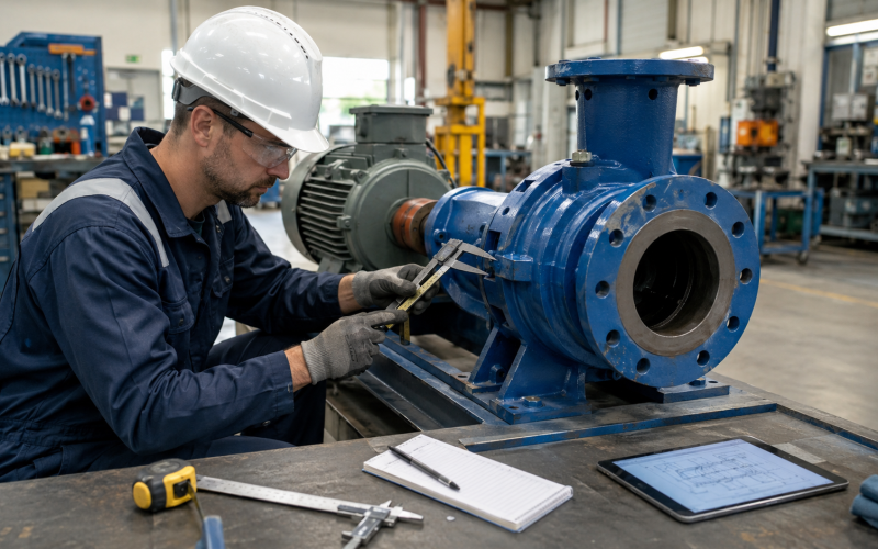
Technical Review Basis: This guide was reviewed using available ASME B73.1 dimensional principles, pump drawings, coupling standards, baseplate specifications and field measurement procedures. Final compatibility must be confirmed for the specific pump and installation.
5 Critical Interfaces to Check Before Replacing an ANSI Process Pump
Replacing an ANSI process pump should not begin with the assumption that every pump carrying an ASME B73.1 designation will fit the existing installation without modification.
The standard aligns important dimensional and design features, but actual installations can still differ by pump size, manufacturer, baseplate, coupling, seal system and previous field modifications.
Before approving a replacement, verify five interface groups: suction and discharge nozzle coordinates; shaft centerline and pump-foot dimensions; shaft extension and coupling position; pump-to-baseplate mounting; auxiliary connections and maintenance clearance.
Key takeaway: The ANSI designation is a starting point, not proof of a drop-in fit. Final compatibility should be confirmed using the exact pump configuration, an approved dimensional drawing and actual site measurements.
This guide focuses on replacing a complete horizontal end-suction process pump or bare pump. Wet-end kits, rotating assemblies and individual components require a different internal-interface inspection.
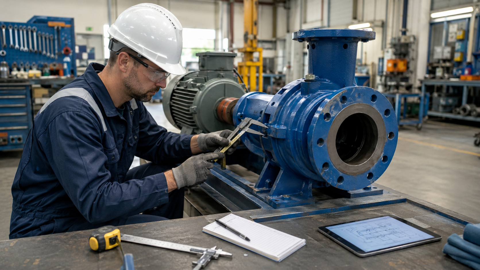
First Define What You Are Replacing
The required measurements depend on the replacement scope.
Complete pump and baseplate: When replacing the complete package, verify process-piping interfaces, foundation bolt pattern, baseplate dimensions, driver position, coupling, guard, maintenance access and overall package footprint.
Bare pump on the existing baseplate: When retaining the existing baseplate and motor, verify nozzle coordinates, pump feet, shaft centerline, shaft extension, distance between shaft ends, coupling position and mounting-bolt pattern.
Back-pullout rotating assembly: When retaining the casing, verify casing-to-frame register, cover or seal-chamber fit, shaft and impeller interfaces, gasket locations, impeller axial position and rotation.
Wet-end kit or individual component: Internal dimensions, hydraulic geometry, material and assembly clearances become the primary concerns. Do not use a complete-pump installation checklist as the only approval document for an impeller, casing or seal chamber.
Interface 1: Suction and Discharge Nozzle Coordinates
The first task is to confirm where each process flange is located in three-dimensional space.
Verify the suction connection: Check nominal flange size, pressure class, facing, bolt-hole quantity, bolt-circle diameter, flange orientation, flange-face location, suction centerline height, suction centerline relative to the shaft and gasket seating surface.
Verify the discharge connection: Check nominal flange size, pressure class, facing, bolt-hole quantity, bolt-circle diameter, discharge centerline elevation, discharge nozzle orientation, flange-face position and rotation around the pump axis.
Why nozzle coordinates matter: A replacement may have the correct nominal flange sizes and still fail to align with the existing piping. Installers should not use flange bolts or pipe force to pull misaligned piping into position. Forced alignment can introduce external nozzle loads and contribute to casing distortion, coupling misalignment, gasket leakage, seal movement and vibration.
How to measure: Use a consistent site reference such as finished baseplate surface, pump mounting plane, shaft centerline or fixed foundation datum. Record horizontal, vertical and axial coordinates rather than relying on one general face-to-face dimension.
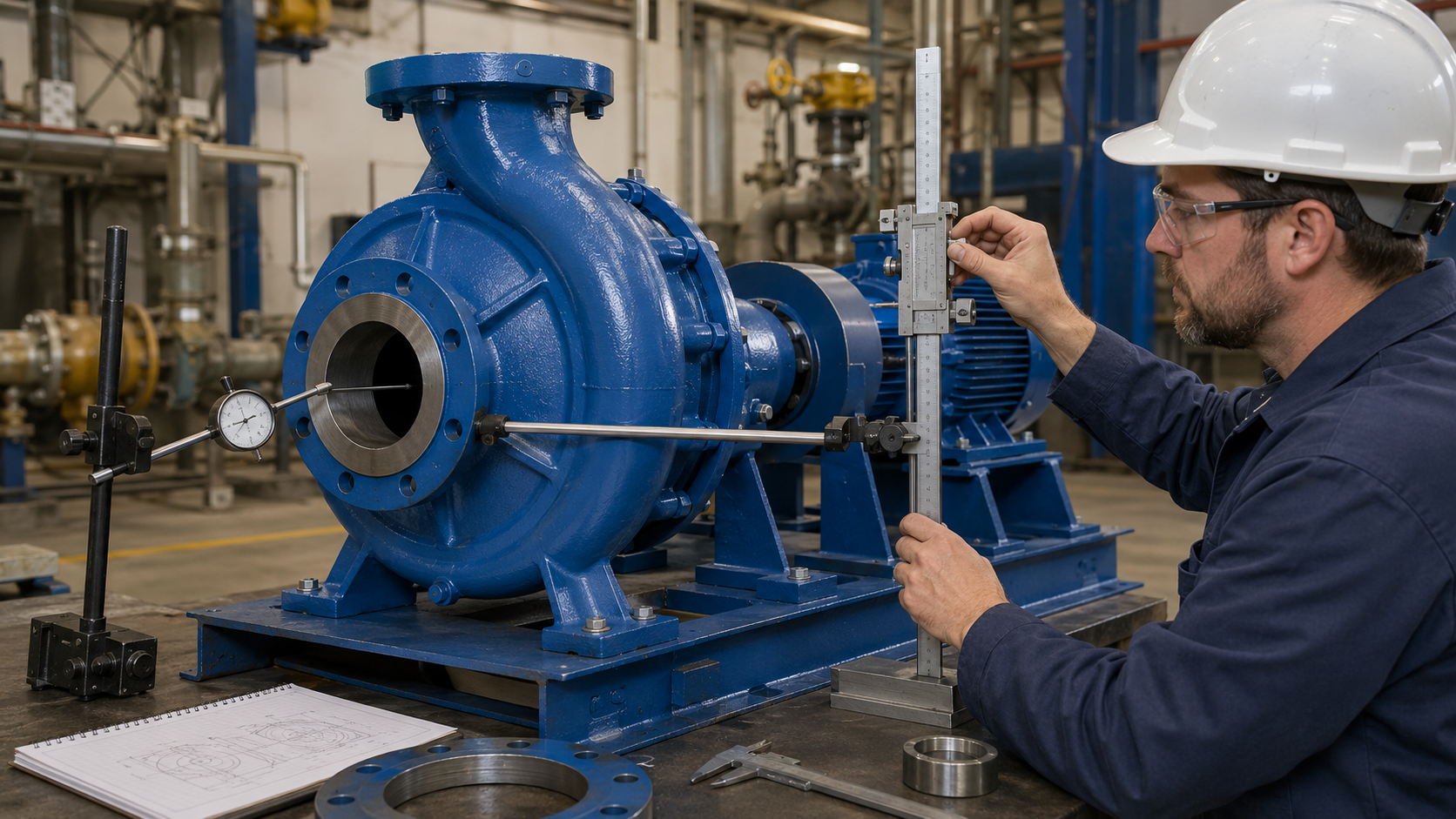
Interface 2: Shaft Centerline and Pump Feet
The replacement shaft must align with the retained driver and coupling arrangement.
Verify shaft centerline height: Measure from the pump mounting surface to the shaft centerline. Do not measure from an uneven foundation, grout surface, corroded baseplate edge or temporary shim pack.
Verify pump feet: Check foot length, foot width, foot thickness, longitudinal bolt spacing, transverse bolt spacing, hole diameter, slot direction, locating shoulder or register and available mounting surface.
Why this matters: A difference in shaft centerline height can require excessive shimming, motor repositioning, coupling changes, guard modification or baseplate machining. A matching shaft height does not by itself prove compatibility. The foot locations and coupling position must also match.
Final installation checks: After setting the pump, check baseplate flatness, identify soft foot, verify shim condition, check free shaft rotation, perform rough alignment, connect piping without forcing the flanges and complete final alignment after piping connection.
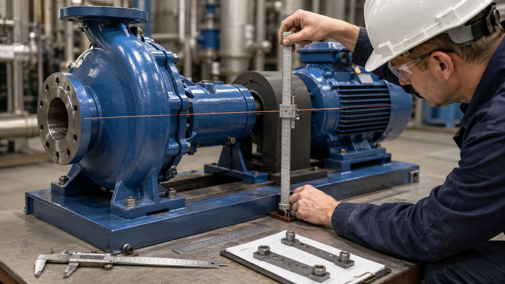
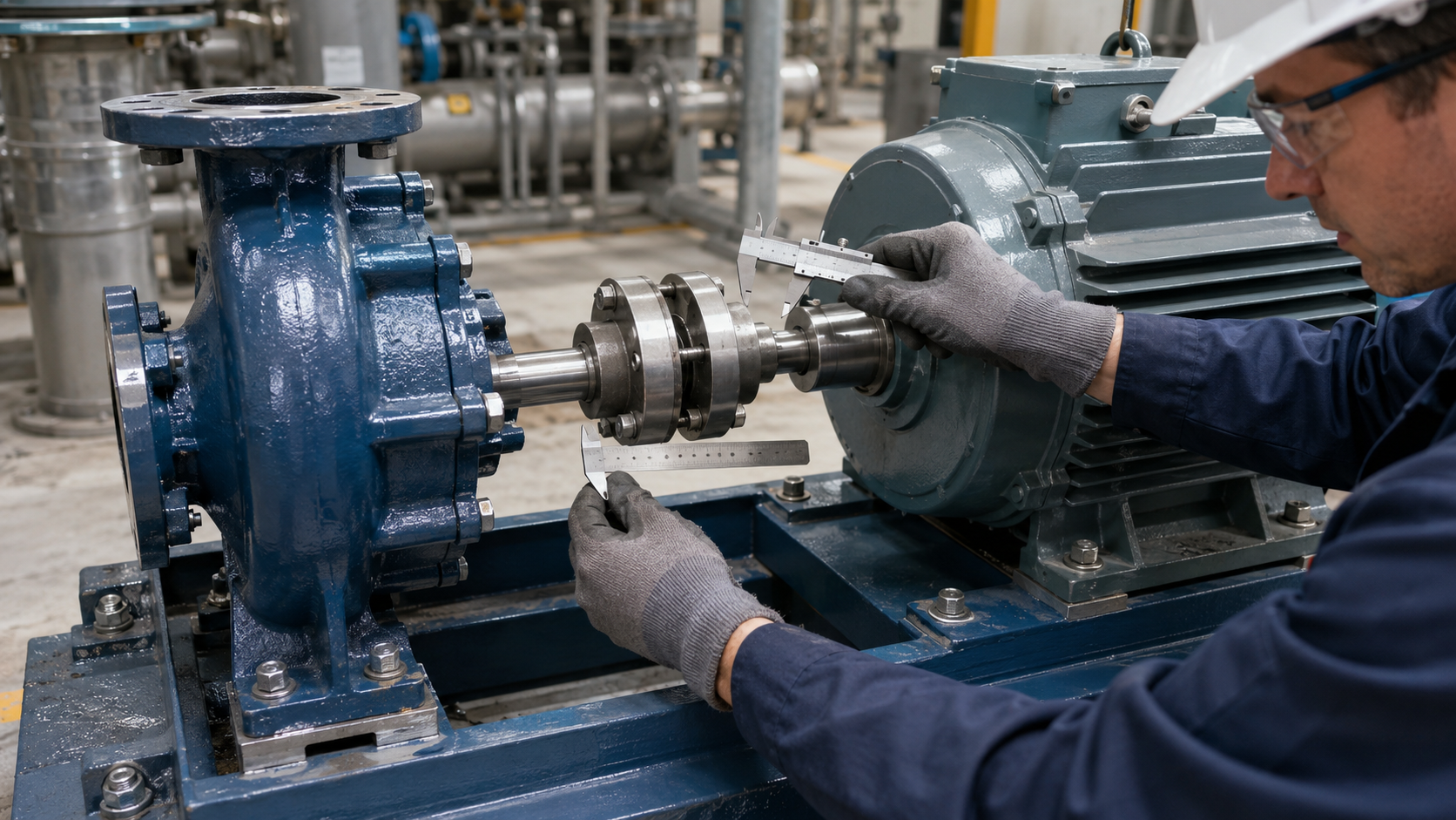
Interface 3: Shaft Extension and Coupling Position
Coupling compatibility is often overlooked because it is not visible in a basic pump footprint comparison.
Verify the shaft extension: Check shaft diameter, shaft extension length, keyway width, keyway depth, key length, shaft-end thread if present, coupling-hub fit and allowable axial position.
Verify coupling geometry: Check coupling type, coupling-hub bore, hub length, distance between shaft ends, spacer length, guard clearance, required axial gap and motor-shaft position.
Why this matters: A replacement can align with the piping and baseplate but still require a different coupling hub, a different spacer, motor movement, guard modification or shaft-end machining. The supplier should not confirm drop-in compatibility without reviewing the coupling arrangement when the existing motor and baseplate will be retained.
Interface 4: Pump-to-Baseplate Mounting
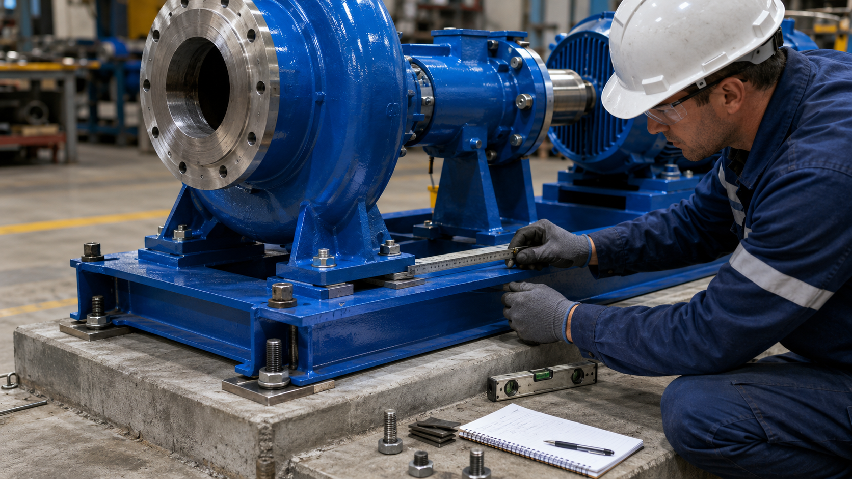
The pump feet connect the pump to the baseplate, but baseplate compatibility involves more than bolt-hole spacing.
Verify: Mounting-pad length and width, longitudinal and transverse hole pattern, hole diameter, threaded or through-hole arrangement, available edge distance, fastener access, shim area, pump overhang, drain-pan or containment interference, maintenance pullout direction, baseplate stiffness and condition.
Existing baseplate condition: Inspect for corrosion, distortion, cracked grout, loose anchor bolts, uneven pads, previous drilling, welded repair plates, excessive shim thickness and motor soft foot. An original drawing may show a compatible bolt pattern while the actual baseplate has been modified during previous repairs.
Interface 5: Auxiliary Connections and Maintenance Envelope
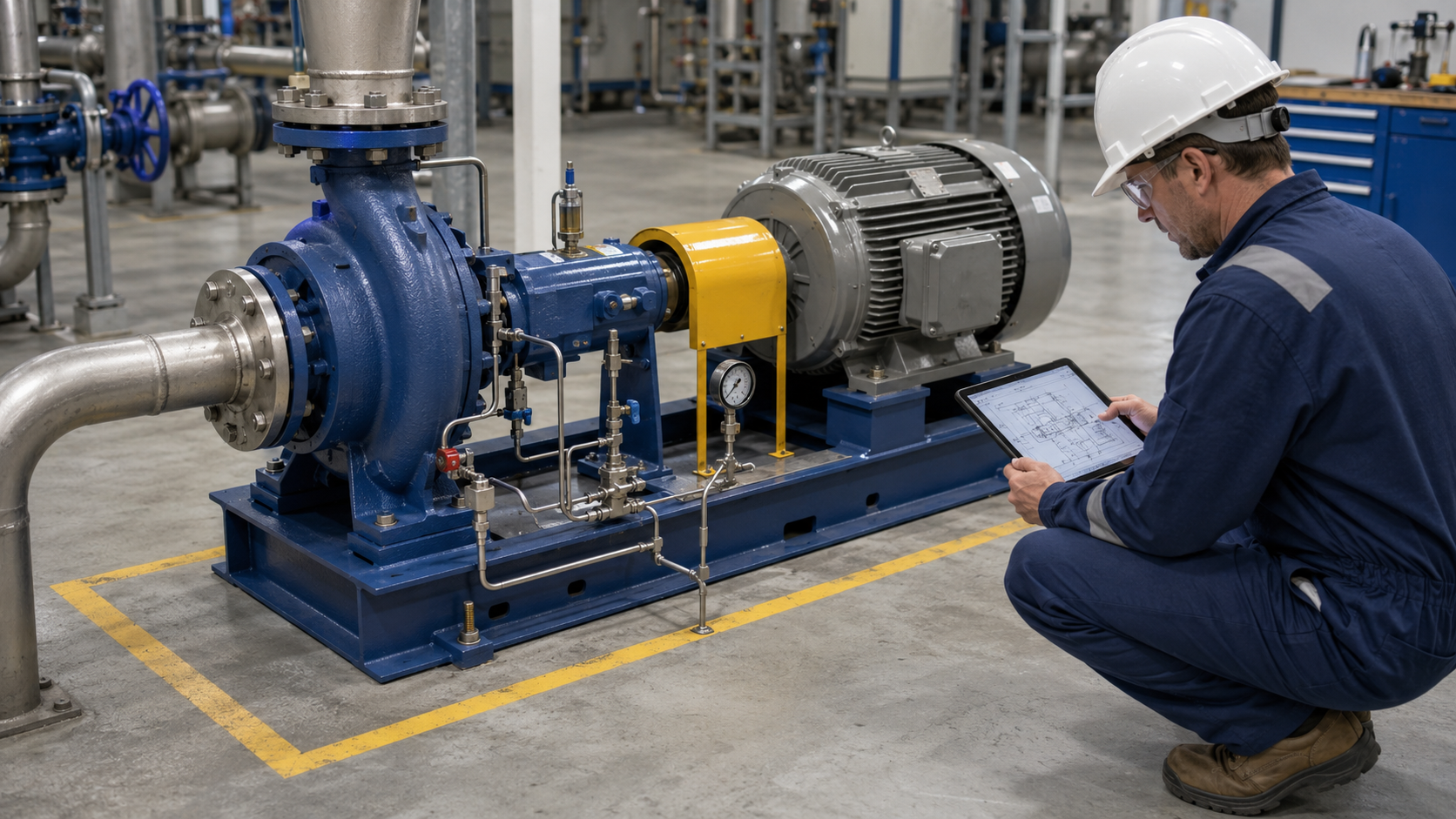
A pump can match the primary flanges and still require significant field work if auxiliary interfaces are different.
Check auxiliary connections: Verify casing drain, casing vent, seal flush, quench, cooling-water connections, pressure-gauge ports, bearing-frame drains, oil-level device, constant-level oiler position and instrumentation connections. Confirm port size, thread type, flange type, orientation, access and required tubing route.
Check seal arrangement: Verify seal chamber type, gland orientation, flush-plan connection, shaft or sleeve diameter, seal support system position and tubing clearance.
Check the maintenance envelope: Confirm there is enough space to remove the coupling spacer, withdraw the back-pullout assembly, remove the seal, lift the motor or pump, access bearing-frame fasteners and use required maintenance tools. A replacement that fits during installation but cannot be serviced without disturbing the piping is not a practical equivalent.
Dimensions Alone Are Not Enough
Even when all installation interfaces match, the replacement must still be reviewed for hydraulic and process suitability.
Hydraulic review: Confirm required flow, differential head, operating speed, impeller diameter, efficiency, absorbed power, NPSHr, available NPSH, minimum continuous stable flow and expected operating range. Matching flange coordinates does not prove that the replacement will produce the required performance.
Motor review: Confirm motor power, service factor, speed, frame, rotation and available power across the operating range.
Material review: Confirm the exact material grades for casing, impeller, shaft, sleeve, seal chamber, gaskets, O-rings and mechanical seal. Material selection should be based on the process fluid, concentration, temperature, solids and corrosion mechanism.
Field Measurement Checklist
Record the following before requesting a replacement quotation:
- Pump identification: Model, size, frame, serial number
- Suction flange: Size, class, facing, centerline and face position
- Discharge flange: Size, class, facing, centerline and orientation
- Shaft: Centerline height, diameter and extension
- Pump feet: Foot size, hole pattern and hole diameter
- Coupling: Type, bore, spacer and distance between shaft ends
- Baseplate: Mounting pads, condition and anchor-bolt pattern
- Auxiliary ports: Size, thread and orientation
- Hydraulic duty: Flow, head, speed, NPSH and motor power
Always identify the reference datum used for each measurement.
Common Reasons a Dimensionally Similar Pump Does Not Fit
- The installed pump was previously modified: baseplate, piping, motor or coupling may no longer match the original drawing
- Only nominal flange size was compared: size alone does not confirm position, orientation, class or drilling
- Shaft centerline was measured from the wrong datum: grout, corrosion and uneven shims can produce an incorrect measurement
- The coupling was ignored: a different shaft extension or spacer requirement can delay installation
- Auxiliary ports were not reviewed: seal-flush or drain connections may require rework
Frequently Asked Questions
Does ASME B73.1 make every ANSI pump interchangeable?
No. It standardizes important dimensional and design features, but exact compatibility still depends on pump size, configuration, manufacturer and installed interfaces.
Can I approve a replacement from the pump nameplate alone?
Usually not. The nameplate is important, but drawings, hydraulic duty, coupling information and site measurements may also be required.
What is the most important pump replacement dimension?
There is no single universal dimension. Nozzle coordinates, shaft centerline, feet, coupling and baseplate must be reviewed as a system.
Can matching nozzle dimensions eliminate repiping?
They may reduce the need for piping modification, but final alignment and piping-strain checks remain necessary.
Can I reuse the existing baseplate?
Possibly. Verify pump-foot dimensions, shaft height, coupling position, mounting-pad condition and available alignment adjustment.
What documents should I send for a replacement review?
Send the pump nameplate, model, size, frame, flow, head, material, seal information, coupling information, drawings and installation photographs.
Request an Installation Compatibility Review
Send us: pump nameplate photograph, pump model size and frame, operating flow and head, material, seal arrangement, coupling information, outline drawing, baseplate drawing and installation photographs.
ANSI Pumps Pro can review the supplied information and identify which dimensions, hydraulic data and material requirements must be confirmed before quotation.