Select a new pump
Know your required flow and head? Compare models and request the applicable curve.
Browse S-Series modelsHorizontal split-case pumps for water transfer and industrial circulation. Compare S-Series models, request curves and drawings, or review an installed pump for replacement.

S-Series split-case pumps · ANSI Pumps Pro
Catalogue limits are configuration-dependent: liquid temperature to 105 °C (221 °F). Flow, head, pressure and temperature maxima are not simultaneous duty guarantees. US units are approximate conversions.
Know your required flow and head? Compare models and request the applicable curve.
Browse S-Series modelsHave an Omega or Omega V? Send the model or nameplate for a duty and interface review.
Review an Omega replacementSearch a model or filter by discharge size. Select a result to view reference data and request the size-specific curve.
Model designation is selectable for every listed model. Only sourced reference points are shown; other hydraulic values require engineering review.
Send the model you searched for plus your duty point. The RFQ can carry the search term automatically.
Request Custom SelectionIn S 150-360, 150 identifies the DN 150 discharge and 360 is the nominal impeller-diameter code. The tabled impeller diameters for this size span 274–355 mm; the code is not a measurement of every fitted impeller.
Where listed, (I) marks the flow-expanded hydraulic variant, G marks a 2900 rpm high-speed version and A denotes the first impeller cut. Available size–speed combinations are listed individually in the catalogue table. Provide the actual motor and pump speed, including 60 Hz or variable-speed requirements.
Manufacturer reference: APP-S-DAT Rev. A, page 3. KSB Omega suffixes are read against the installed pump’s own documentation.
Compare the full reference configuration, including its (I) flow-expanded variant. The size directory groups different variants and impellers for preliminary screening.
| Reference configuration | Reference flow | Reference head | Reference speed |
|---|---|---|---|
| S 125-500(I) | 328 m³/h≈ 1,444 US gpm | 76 m≈ 249 ft | 1450 rpm |
| S 150-360(I) | 446 m³/h≈ 1,964 US gpm | 38 m≈ 125 ft | 1450 rpm |
| S 200-520(I) | 817 m³/h≈ 3,597 US gpm | 91 m≈ 299 ft | 1450 rpm |
| S 250-600(I) | 1,242 m³/h≈ 5,468 US gpm | 116 m≈ 381 ft | 1450 rpm |
| S 300-435(I) | 1,677 m³/h≈ 7,384 US gpm | 53 m≈ 174 ft | 1450 rpm |
These values belong to the configurations and duty points listed above, all at 1450 rpm.
| Configuration | Shaft power | Motor rating | NPSHr | Impeller |
|---|---|---|---|---|
| S 125-500(I) | 82.7 kW | 110 kW | 2.8 m | 475 mm |
| S 150-360(I) | 54.3 kW | 75 kW | 3.0 m | 355 mm |
| S 200-520(I) | 241 kW | 280/315 kW | 4.0 m | 530 mm |
| S 250-600(I) | 467 kW | 560 kW | 4.6 m | 610 mm |
| S 300-435(I) | 275 kW | 315 kW | 7.1 m | 450 mm |
Shaft power is absorbed by the pump at the listed point; motor rating is the driver size. Compare available NPSH with the selected pump’s NPSHr and required engineering margin.
| Size | rpm | Flow range, m³/h | Head range, m | Largest catalogue motor, kW | Source |
|---|---|---|---|---|---|
| S 80-210 | 1450 | 47–100 | 6.5–15 | 5.5 | p. 3 |
| S 80-210 | 2900 | 91–197 | 27–60.5 | 37 | p. 3 |
| S 80-270 | 1450 | 53–125 | 10.8–24 | 11 | p. 3 |
| S 80-270 | 2900 | 110–248 | 42–97.5 | 75 | p. 3 |
| S 80-370 | 1450 | 53–136 | 17.5–41 | 22 | p. 3 |
| S 100-250 | 1450 | 75–173 | 9.5–21.2 | 11 | p. 3 |
| S 100-250 | 2900 | 150–346 | 37–83 | 90 | p. 3 |
| S 100-310 | 1450 | 94–222 | 15–34 | 22 | p. 3 |
| S 100-310 | 2900 | 182–440 | 60–135 | 200 | p. 3 |
| S 100-375 | 1450 | 92–220 | 25–57 | 45 | p. 3 |
| S 125-230 | 1450 | 156–328 | 6.8–17 | 18.5 | p. 3 |
| S 125-230 | 2900 | 305–639 | 30–68 | 132 | p. 3 |
| S 125-290 | 1450 | 138–323 | 11.3–29.2 | 30 | p. 3 |
| S 125-290 | 2900 | 274–640 | 47–117 | 200 | p. 3 |
| S 125-365 | 1450 | 158–360 | 20.9–50 | 75 | p. 3 |
| S 125-500 | 1450 | 161–393 | 40–82 | 110 | p. 3 |
| S 150-290 | 1450 | 265–531 | 9.8–24 | 37 | p. 3 |
| S 150-360 | 1450 | 233–536 | 16.7–41.3 | 75 | p. 3 |
| S 150-460 | 1450 | 260–618 | 28.2–71 | 132 | p. 3 |
| S 150-605 | 1450 | 323–700 | 50–112 | 250 | p. 3 |
| S 200-320 | 1450 | 412–834 | 14.2–34 | 75 | p. 3 |
| S 200-420 | 1450 | 375–850 | 24–57 | 132 | p. 3 |
| S 200-520 | 1450 | 478–980 | 38–97 | 315 | p. 3 |
| S 200-670 | 1450 | 455–936 | 73–157.5 | 500 | p. 3 |
| S 250-370 | 1450 | 680–1,260 | 16–44 | 160 | p. 3 |
| S 250-480 | 1450 | 527–1,408 | 28.5–95.5 | 280 | p. 3 |
| S 250-600 | 1450 | 640–1,490 | 56.5–126 | 560 | p. 3 |
| S 300-300 | 1450 | 560–1,318 | 7.5–28.8 | 110 | p. 3 |
| S 300-435 | 1450 | 1,066–2,012 | 24–60 | 315 | p. 3 |
| S 300-560 | 1450 | 1,026–2,095 | 41–101.5 | 630 | p. 3 |
| S 350-360 | 1450 | 950–2,077 | 9–37.5 | 200 | p. 3 |
| S 350-430 | 1450 | 1,486–3,292 | 15–49.5 | 450 | p. 3 |
| S 350-510 | 1450 | 1,555–3,132 | 30–80 | 630 | p. 3 |
| S 350-620(I) | 1450 | 1,020–2,640 | 69–139 | 1,000 | p. 3 |
| S 350-700 | 1450 | 1,074–2,082 | 71.5–170 | 1,120 | p. 3 |
| S 400-540 | 1450 | 1,110–3,420 | 33–98.5 | 900 | p. 3 |
| S 400-620 | 1450 | 1,265–4,100 | 49.8–129.5 | 1,400 | p. 3 |
| S 500-510 | 960 | 1,365–3,925 | 8–33 | 280 | p. 3 |
| S 500-640 | 960 | 1,530–4,500 | 18–52.5 | 500 | p. 3 |
| S 500-700 | 960 | 1,450–5,040 | 26.5–73 | 1,000 | p. 3 |
| S 500-790 | 960 | 1,710–5,150 | 36–88.5 | 1,250 | p. 3 |
| S 500-890 | 960 | 1,840–5,500 | 56–124 | 1,800 | p. 4 |
| S 600-540 | 960 | 1,890–6,080 | 8.5–33.7 | 400 | p. 4 |
| S 600-620 | 960 | 1,770–5,940 | 18–48 | 630 | p. 4 |
| S 600-710 | 960 | 1,740–6,050 | 27–69 | 900 | p. 4 |
| S 600-830 | 960 | 2,080–6,950 | 32–105 | 1,800 | p. 4 |
| S 700-590 | 960 | 2,610–8,060 | 10–38.8 | 710 | p. 4 |
| S 700-710 | 960 | 2,780–8,460 | 21–58.5 | 1,000 | p. 4 |
| S 700-820 | 960 | 2,340–9,600 | 35.5–92 | 2,000 | p. 4 |
| S 800-740 | 725 | 3,760–11,000 | 10.5–37.8 | 800 | p. 4 |
| S 800-840 | 725 | 3,630–11,700 | 16.8–56.4 | 1,400 | p. 4 |
| S 800-970 | 725 | 3,840–11,600 | 25–75.5 | 2,000 | p. 4 |
Ranges combine catalogue points across different impeller diameters and variants. Flow and head range endpoints are not paired duty points; a single trim has a narrower curve. The listed motor is the largest catalogue motor for that size–speed group, not the power required at your duty. S 350-620 is listed only in its (I) configuration.
Reference configurations: APP-S-CONFIG Rev. A, compiled from the S-Series catalogue (11 March 2026), original pages 23, 25, 31, 35 and 37. Size–speed ranges: APP-S-DAT Rev. A, pages 3–4. Range endpoints are separate from individual duty points.
Confirm flow, head, efficiency, NPSHr, speed and impeller selection against the verified curve for the selected model.
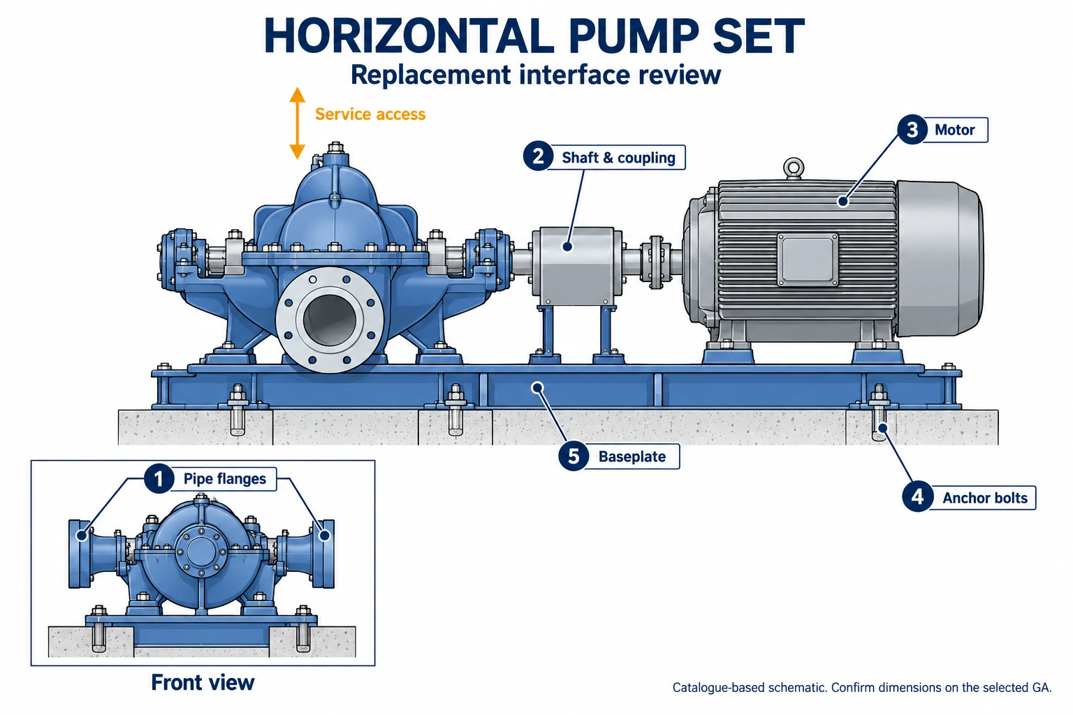
Request Individual Performance CurveUse the approved GA to confirm flange position, nozzle centerline, shaft height, baseplate footprint and anchor-bolt interfaces.
Request GA DrawingReview duty point, speed, NPSH and system conditions before confirming a pump selection.
Split-Case Sizing and NPSH GuideShare the installed model or nameplate to start a hydraulic and dimensional replacement review.
Start Replacement ReviewCheck the selected pump and driver arrangement against the pipe connections, foundation and service access. The catalogue includes horizontal pump-set dimensions and vertical OA / OB arrangement references.
Use coverage diagrams for preliminary model screening. Request the individual Q/H, power, efficiency and NPSHr curves for the actual speed and trim before confirming a duty.
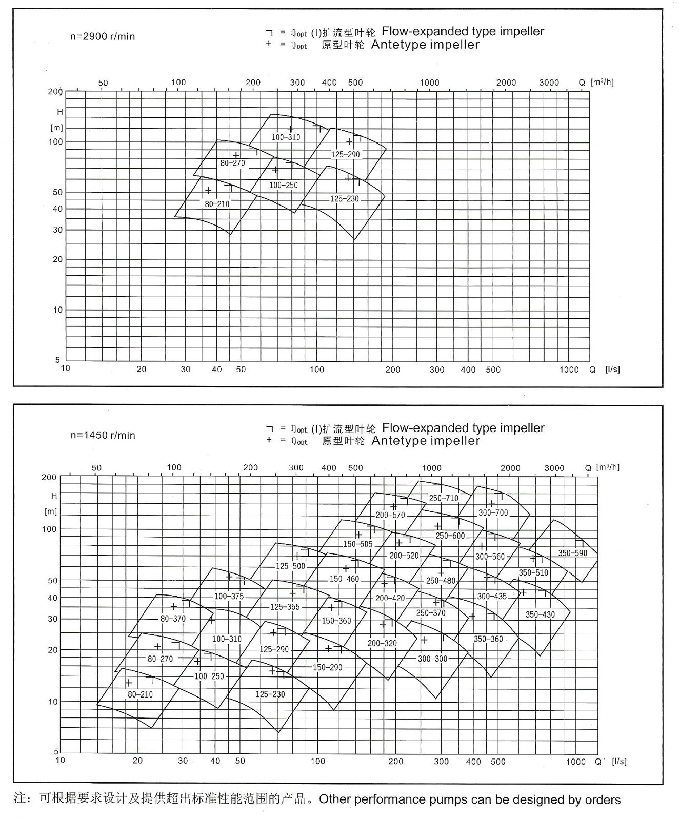
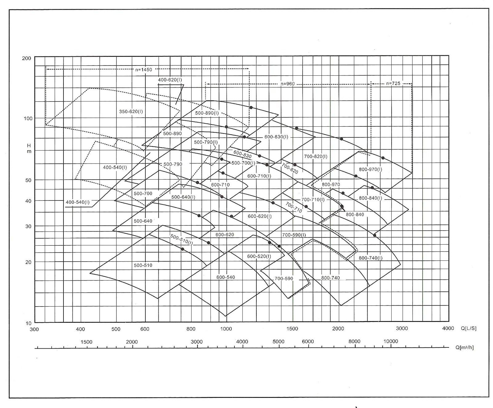
The original coverage diagrams contain some chart-only designations not listed in the size table. Use the catalogue table for the published size–speed directory; engineering confirms any additional configuration. The fields shown are envelopes rather than individual performance curves.
Send the installed model, nameplate, duty point and available GA information. We review the hydraulic duty and installation interfaces before confirming the replacement configuration.
Where the installed configuration is verified as a direct match, we can supply a 100% dimensional replacement.
Where an interface differs, the engineering review and quotation will identify the difference and define any required transition baseplate, spool arrangement or other adaptation before production.
Start Omega Replacement ReviewManufacturing and test scope are confirmed for the selected pump and agreed project requirements.
Use the approved model drawing and datasheet to confirm the final construction for each project.
Liquid enters the impeller from both sides, helping balance axial hydraulic force and support high-flow service. Confirm the final duty point against the approved performance curve.
The upper casing can be removed for inspection of the rotor and impeller while the main suction and discharge piping remains connected, subject to installation access.
Bearing options and mechanical seal or packing arrangements are selected for the service. Confirm the final arrangement on the project datasheet and order documents.
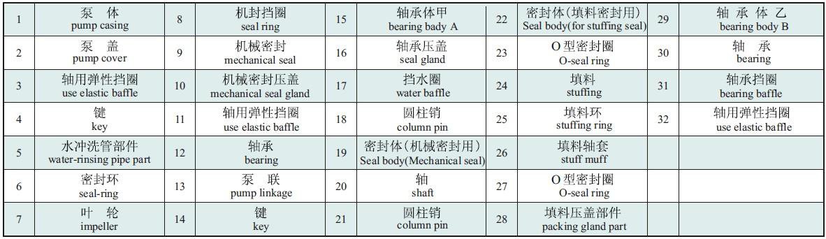
Use the manufacturer’s numbered sectional reference to identify the casing, impeller, shaft, bearings and seal arrangements. Submit a drawing reference and item number when asking about a component.
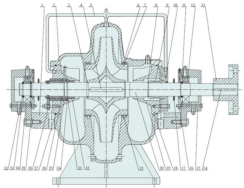
Match the item number in the sectional drawing to the component below.Scroll within the list to view all 32 items.
| Item | Component |
|---|---|
| 1 | Pump casing |
| 2 | Pump cover |
| 3 | Shaft retaining ring |
| 4 | Key |
| 5 | Rinse-pipe assembly |
| 6 | Seal ring |
| 7 | Impeller |
| 8 | Mechanical-seal retaining ring |
| 9 | Mechanical seal |
| 10 | Mechanical-seal gland |
| 11 | Shaft retaining ring |
| 12 | Bearing |
| 13 | Pump coupling |
| 14 | Key |
| 15 | Bearing housing A |
| 16 | Bearing cover |
| Item | Component |
|---|---|
| 17 | Water deflector |
| 18 | Cylindrical pin |
| 19 | Mechanical-seal housing |
| 20 | Shaft |
| 21 | Cylindrical pin |
| 22 | Packing-seal housing |
| 23 | O-ring |
| 24 | Packing |
| 25 | Packing ring |
| 26 | Packing sleeve |
| 27 | O-ring |
| 28 | Packing-gland assembly |
| 29 | Bearing housing B |
| 30 | Bearing |
| 31 | Bearing retaining ring |
| 32 | Shaft retaining ring |
These numbers belong to this S-Series illustration. They are not KSB order numbers, a universal Omega BOM or a promise that every configuration uses the same parts.
Material selection must be verified against the actual liquid, temperature, corrosion conditions and project specification. ASTM / EN equivalence requires engineering confirmation.
Swipe to view material grades and options →
| Component | Catalog material | Catalogue grade / international reference | Engineering action |
|---|---|---|---|
| Pump casing | Grey Cast Iron / Ductile Iron / Cast Steel | HT250 (grey iron; compare EN-GJL-250 / ASTM A48)QT400-18 (ductile iron; compare EN-GJS-400-18-RT / ASTM A536 60-40-18)ZG230-450 (cast steel; ASTM A216 WCB comparison) | |
Pump casing material review Choose only from the catalog-supported casing materials below. Service suitability for seawater or strongly corrosive liquids requires engineering confirmation. | |||
| Impeller | Bronze / Grey Cast Iron / Silicon Brass / Stainless Steel | ZCuSn10Pb1 (tin bronze; specify the ASTM B584 alloy)HT250 (grey iron; compare EN-GJL-250 / ASTM A48)ZCuZn16Si4 (silicon brass)ZG1Cr18Ni9Ti (cast stainless steel) | |
Impeller material review Select a catalog-listed impeller material. Corrosion suitability must be confirmed against the actual pumped liquid and temperature. | |||
| Shaft | Stainless Steel / Carbon Steel | 2Cr13 (13% Cr stainless; compare AISI 420 / EN 1.4021)45# (carbon steel) | |
Shaft material review Select from the two shaft materials explicitly listed in the approved product information. | |||
| Casing seal ring | Bronze / Grey Cast Iron / Silicon Brass / Stainless Steel | ZCuSn10Pb1 (tin bronze; specify the ASTM B584 alloy)HT250 (grey iron; compare EN-GJL-250 / ASTM A48)ZCuZn16Si4 (silicon brass)ZG1Cr18Ni9Ti (cast stainless steel) | |
Casing seal ring material review Select a catalog-listed seal-ring material and confirm the final metallurgy during engineering review. | |||
EN / ASTM references guide specification review; they are not certified grade substitutions. Confirm composition, mechanical properties, section thickness, heat treatment and the required material certificate for the selected component.
ASTM A48 covers grey iron, ASTM A536 covers ductile iron and ASTM A216 covers cast carbon steel, including WCB. Select the actual grade against the project specification. For ZCuSn10Pb1, specify the required ASTM B584 alloy and chemistry rather than assume UNS C90500 equivalence. For 2Cr13, confirm the shaft condition and required heat treatment.
References: ASTM A48; ASTM A536; ASTM A216; CDA C90500 composition; Outokumpu Dura stainless grades.
Cooling-water systems often move high flow through circulating loops. A split-case layout may suit duties where service access around a double-suction pump is useful. Confirm flow and head across operating points, water temperature, system losses and available suction NPSH.
Chilled-water and district-cooling loops can require sustained circulation across changing seasonal loads. Split-case architecture may suit high-flow duties where the site can accommodate its footprint. Confirm seasonal flow, differential head, speed control and NPSH at each operating point.
Municipal transfer and distribution duties may require high flow and continuous operation. Split-case architecture can provide upper-casing access during maintenance, subject to the installed arrangement. Confirm peak and minimum demand, suction level, water quality and connection standards.
Cooling-water and auxiliary circulation can combine large flows with defined availability needs. A split-case pump may be considered after checking the duty and service access. Confirm water temperature, fouling or solids, suction conditions, redundancy and project test requirements.
Irrigation networks and drainage stations may see seasonal operation and changing flow demand. A split-case pump may suit high-capacity transfer where installation geometry allows. Confirm source-level variation, required head, solids content, seasonal flow range and suction NPSH.
Industrial water and utility systems may transfer bulk flow between tanks, process units or cooling circuits. A split-case pump may suit high-flow service with materials and seals matched to the liquid. Confirm solids, temperature, corrosion exposure, duty cycle and pump curve.
Start with flow, head, liquid, temperature, speed and installation constraints before selecting a model.
Send the existing pump model, nameplate, duty point or GA drawing. A model number or nameplate photo is enough to start the replacement review.
Our manufacturing and release process includes casting spectrometer and chemical checks, hydrostatic testing, impeller balancing and a performance-curve test. Specify the required records when requesting a quotation.
Request the required material grade and component specification. Chemical analysis and the applicable mechanical-property records establish the material acceptance basis.
Agree the dimensional checks, hydrostatic and performance-test conditions, acceptance criteria and witness points for the selected pump.
EN 10204 3.1 records, witness testing and third-party inspection can be included in the agreed project scope. Approved GA and interface records define the installation configuration.
Manufacturing reference: APP-S-DAT Rev. A, page 5. State ASTM/EN requirements explicitly in the inquiry; material equivalence is reviewed for the component and specified standard.
Send a duty point, model, nameplate photo or drawing. A nameplate photo is enough to start the replacement review; GA details can be checked during engineering follow-up.
Choose the project mode, describe the requirement and attach any available nameplate, drawing or specification.
Replacement component requests are reviewed for casing, cover, impeller, shaft and selected metallic mechanical-seal components. Availability depends on the installed model and service review.
It identifies a flow-expanded hydraulic variant in the S-Series catalogue. Match the full designation, speed and impeller details when comparing performance data.
The catalogue lists shaft power and motor rating separately. Shaft power changes with the operating point; review the motor against the required operating range and service conditions.
Send the actual pump speed, required flow and head, liquid and suction conditions. Engineering reviews the curve and motor for the proposed speed. Use listed catalogue values at their stated rpm.
Request the model and arrangement-specific drawing. Include motor, coupling and supply scope when a complete pump-set layout is required.
Yes. We review the installed pump's duty, materials and interface dimensions before selecting a replacement and supply scope. Use the dedicated KSB Omega and Omega V replacement review or Sulzer ZPP replacement review. For other makes, send the full model, nameplate and available GA drawing.
Potentially. Shaft height, coupling spacing, motor arrangement and baseplate interfaces must be verified first.
Existing brand/model, nameplate photo, flow, head, speed and GA drawing if available.
Start with required flow and head, operating speed and available NPSH. The final model and impeller selection must be checked against the verified performance curve and system conditions.
Model-specific verified performance information can be provided during engineering review where available. Confirm the selected curve and operating point for the project before ordering.
Review flange position, nozzle centerline, shaft height, baseplate and anchor-bolt interfaces, and coupling dimensions alongside the hydraulic duty.
No. The installed model or nameplate can start the review. A GA drawing may be requested before final dimensional confirmation.