
Pump System Hydraulic Calculation Spreadsheet
This pump system hydraulic calculation spreadsheet is an Excel workbook for tracing pipe-system pressure loss and centrifugal pump duty from entered process and piping data. It is a workbook-based calculation reference, while the online calculator remains available for the primary calculator intent.
Download Excel Workbook Use Online Pump System Hydraulic Calculator Request an engineering review
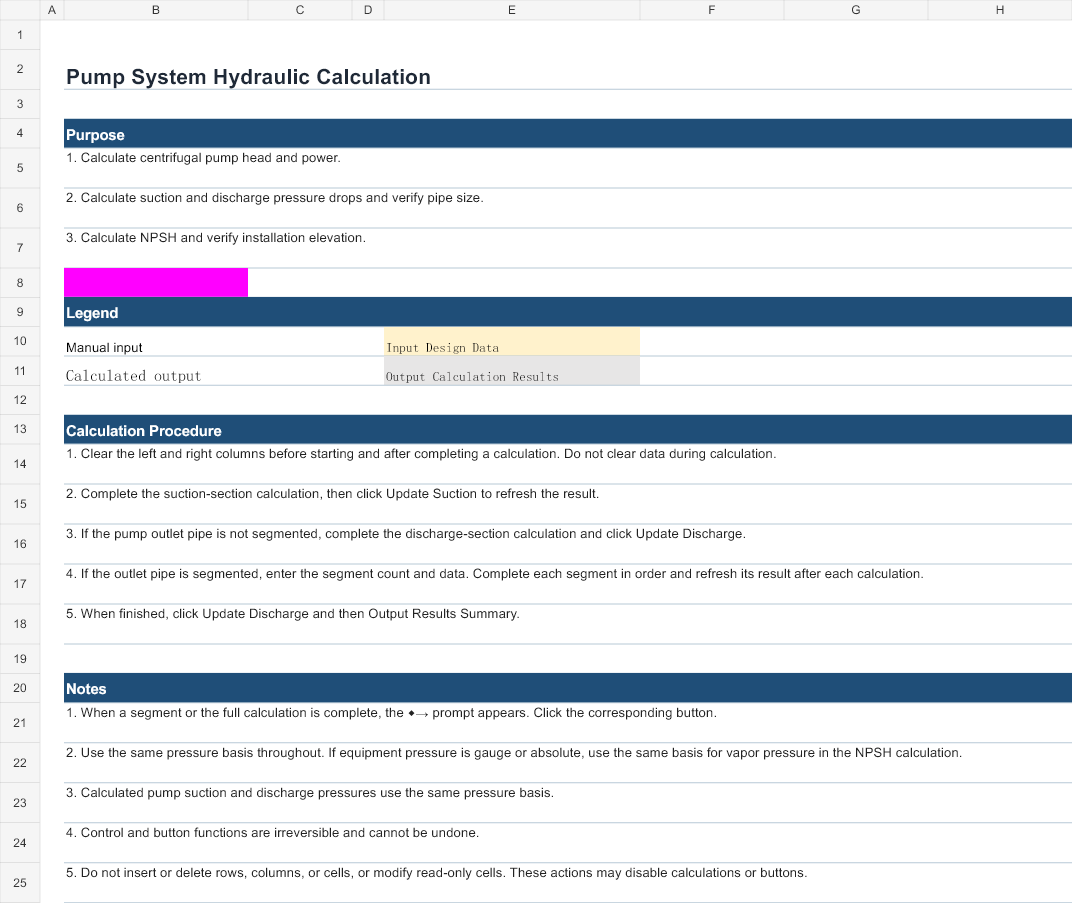
Workbook scope
The workbook contains four visible worksheets:
- Home — purpose, calculation procedure, notes and references supplied in the workbook.
- Process Calculation — pressure-drop sections, suction and discharge calculations, pump head, power and NPSH-related calculations.
- Results Summary — labeled suction, discharge and pump output summary.
- Results Output — output presentation for the same calculation flow.
Inputs and outputs
Inputs
The audited workbook exposes flow rate, pipe inner diameter, straight-pipe length, elevation or liquid-level terms, density, viscosity, vapor pressure, pipe wall absolute roughness, equipment pressures, equivalent lengths or fitting quantities, pump efficiency and a required-suction input labeled NPSHr. Units displayed by the workbook include m³/h, mm, m, kg/m³, mPa·s, kPa, m/s, kW and m.
Outputs
Audited output labels include inlet and outlet velocity, static pressure drop, total friction pressure drop, suction and discharge pressure, equivalent head, pump required pressure, pump head, hydraulic power, shaft power, NPSH Available and NPSH Margin.
Calculation basis
The formula chain is visible in the workbook. It uses continuity for velocity, Reynolds number and friction-coefficient logic, straight-pipe friction, local fitting loss, equipment entry or exit pressure loss, elevation pressure terms, pressure-to-head conversion, pump required pressure and power relationships. Results Summary and Results Output link back to the Process Calculation sheet.
The workbook instructs users to keep the same pressure basis throughout the calculation. Its process flow distinguishes suction-side and discharge-side terms and supports segmented discharge sections.
Recalculated worked example
The following representative example was independently recalculated from the workbook’s stored default inputs and formula text. It is shown to document the workbook’s calculation path, not as a universal design recommendation.
| Item | Value | Unit |
|---|---|---|
| Density | 1000 | kg/m³ |
| Flow rate used in hydraulic example | 200 | m³/h |
| Pipe inner diameter | 200 | mm |
| Velocity | 1.7684 | m/s |
| Reynolds number | 353,677.65 | dimensionless |
| Friction coefficient | 0.04485 | dimensionless |
| Pump required pressure | 149.7260 | kPa |
| Pump head | 15.2626 | m |
| NPSH Available | 3.2569 | m |
| Required suction input | 2 | m |
| NPSH margin reported by formula | 1.2569 | m |
| Hydraulic power calculation | 4.1587 | kW |
| Shaft power calculation | 5.1984 | kW |
Limitations
- This page describes the published workbook only. It does not transfer every feature of the online calculator to Excel.
- The workbook contains hidden rows and columns used by its calculation flow. Do not insert or delete rows, columns or cells, and follow the workbook’s own update sequence.
- The workbook’s Home sheet states that control and button functions are irreversible and cannot be undone.
- Use one consistent pressure basis for equipment pressure and vapor-pressure inputs.
- NPSHa is derived from the system-side terms in this workbook. NPSHr is a required-suction input and must come from the selected pump or manufacturer data; this page does not invent it.
- Confirm duty point, operating range, pump curve, NPSHr and site conditions with the responsible engineer before selection or release.