
Total Dynamic Head Calculation Spreadsheet
This total dynamic head calculation spreadsheet is an Excel workbook for a preliminary pump-head calculation from flow, fluid, elevation, pressure, pipe and local-resistance inputs. The workbook is a spreadsheet calculation reference. The online calculator remains the primary calculator intent.
Download Excel Workbook Use Online TDH Calculator Request an engineering review
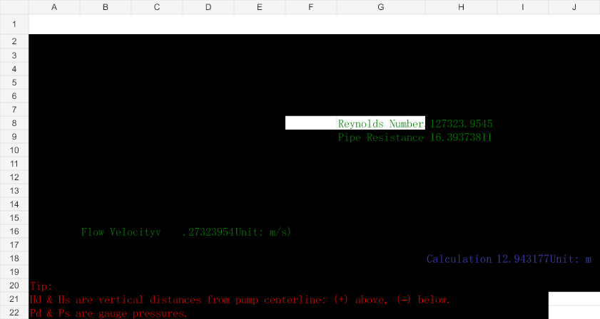
Workbook facts
The published workbook contains three visible worksheets:
- Main Calculator — inputs, Reynolds number, pipe resistance and final calculation result.
- Pipe Roughness Ref — absolute roughness reference values.
- Local Resistance Ref — local resistance coefficient reference values for fittings and valves.
The workbook contains no macros, external links or named ranges. Its calculation result is displayed in metres.
Inputs
- Pump flow rate, entered in m³/s.
- Fluid density in kg/m³ and viscosity in Pa·s.
- Discharge height
Hdand suction heightHs, in metres. - Pump discharge pressure
Pdand pump suction pressurePs, in MPa gauge. - Pipe inner diameter, straight-pipe length and absolute roughness, in metres.
- Local resistance coefficient
ζ.
Outputs
- Flow velocity
vin m/s. - Reynolds number
Re. - Pipe resistance, representing the friction and local-loss head terms.
- Calculation Result in metres, used here as the workbook’s total dynamic head / required pump-head result.
Calculation basis
The workbook calculates velocity in D16 using 4Q/(πd²). It calculates Reynolds number in H8 using D16 × d × ρ / μ. The pipe-resistance result in H9 uses a laminar branch of 64/Re and a turbulent branch using the workbook’s logarithmic friction expression, together with straight-pipe length, diameter, roughness and the local-resistance term.
The final workbook result is the exact formula in I18:
I18 = D7 + D8 + H9 + D9 × 1,000,000 / (G5 × 9.81) − D10 × 1,000,000 / (G5 × 9.81)
The workbook’s own note states that Hd and Hs are vertical distances from the pump centerline and that positive means above while negative means below. The formula therefore uses the signed inputs as D7 + D8. The workbook also states that Pd and Ps are gauge pressures, so the pressure term is based on their difference on that gauge basis.
Recalculated worked example
The following example uses the workbook’s stored default inputs and independently reproduces the formula chain:
| Input or result | Value | Unit |
|---|---|---|
| Flow rate | 0.01 | m³/s |
| Fluid density | 1000 | kg/m³ |
| Fluid viscosity | 0.001 | Pa·s |
| Discharge height Hd | 10 | m |
| Suction height Hs | 5 | m |
| Discharge pressure Pd | 1 | MPa gauge |
| Suction pressure Ps | 0.2 | MPa gauge |
| Pipe diameter | 0.1 | m |
| Pipe length | 1000 | m |
| Roughness | 0.0001 | m |
| Local resistance coefficient ζ | 0.75 | dimensionless |
| Velocity D16 | 1.2732395447 | m/s |
| Reynolds number H8 | 127,323.9545 | dimensionless |
| Pipe resistance H9 | 16.3937381089 | m |
| Calculation Result I18 | 112.9431774565 | m |
How to use
- Enter flow, fluid, elevation, pressure and pipe data in the Main Calculator sheet.
- Keep pressure inputs on the workbook’s stated gauge basis.
- Use signed elevation values according to the workbook’s centerline convention.
- Use the Pipe Roughness Ref and Local Resistance Ref sheets to select defensible input values.
- Review the Calculation Result in metres and check the duty point against the selected pump documentation.
Limitations
- This is a preliminary workbook calculation, not a final pump selection or certified system design.
- The source workbook uses gauge pressure inputs. Do not mix gauge and absolute pressure values without an explicit conversion outside the workbook.
- The source workbook uses signed suction and discharge heights in the exact formula shown above. Do not silently replace that convention with a different elevation convention.
- The local-loss treatment is represented by a single local resistance coefficient input and the workbook’s pipe-resistance formula.
- Confirm actual pipe data, fittings, operating conditions, manufacturer pump curves and required operating margin with the responsible engineer.
- No universal design margin or unsupported engineering standard is added by this page.
Spreadsheet and online calculator
The spreadsheet exposes its three source worksheets and formula path for review. The online TDH calculator is a separate tool for the calculator intent and may not expose the same workbook layout.