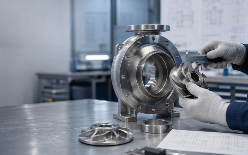
Quick answer: A Goulds 3196 or Durco Mark III wet-end replacement should not be ordered by model name alone. Confirm the pump group, frame size, nozzle orientation, seal chamber, shaft sleeve, impeller clearance, and material before purchase.
What this guide covers
This guide explains the dimensions and operating information that should be checked when evaluating a replacement wet end for Goulds 3196 and Durco Mark III process pumps. It is a purchasing and installation reference, not a blanket promise that every pump of the same nominal size is interchangeable.
- ANSI frame and pump size identification
- Wet-end, seal chamber, shaft sleeve, and impeller checks
- Material selection for chemical service
- Pre-installation measurements and documentation
Important limitation: Compatibility depends on the exact pump group, frame arrangement, seal configuration, operating conditions, and actual field measurements. Ask for a dimensional review when replacing a complete assembly or changing materials.
1. Dimensions to verify before ordering
Use the following checklist with the nameplate, existing pump, OEM drawing, or field measurements. A nominal 3×2-13 or 4×3-13 designation is not enough by itself.
| Check | Why it matters | What to provide |
|---|---|---|
| Pump group and frame | Determines the bearing frame, shaft arrangement, and wet-end envelope. | Nameplate photo and complete model code. |
| Suction and discharge orientation | Prevents piping rework and nozzle misalignment. | Photos or a simple orientation sketch. |
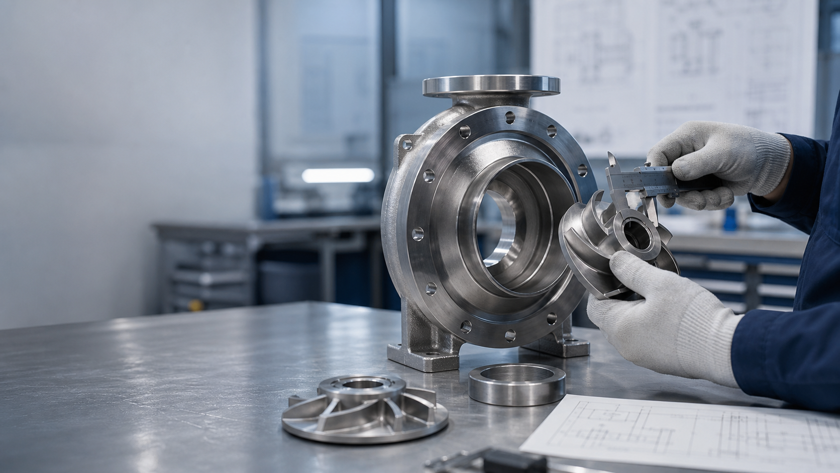
| Seal chamber and sleeve | Controls mechanical-seal fit, sleeve diameter, and gland arrangement. | Seal type, sleeve diameter, and chamber measurements. |
| Impeller diameter and clearance | Influences hydraulic performance, power, and casing clearance. | Impeller diameter, trim, and service duty. |
| Material and temperature | Must match the fluid, concentration, solids, corrosion, and temperature. | Fluid composition, temperature, density, and solids content. |
2. Goulds 3196 and Durco Mark III interchange considerations
Replacement wet ends are normally evaluated against a dimensional envelope rather than a brand label. The dimensions below are examples of the information that should be checked; they are not a substitute for the drawing or measurement of the specific pump.
| Interface | Verify | Typical review result |
|---|---|---|
| Mounting and casing | Frame size, bolt pattern, casing feet, and face-to-centerline dimension. | Proceed only when the replacement drawing matches the same frame arrangement. |
| Nozzles | Flange class, bolt circle, nozzle size, and orientation. | Confirm against piping before calling it a drop-in replacement. |
| Seal interface | Chamber bore, sleeve diameter, gland, flush or quench ports. | Mechanical seal may require a separate configuration review. |
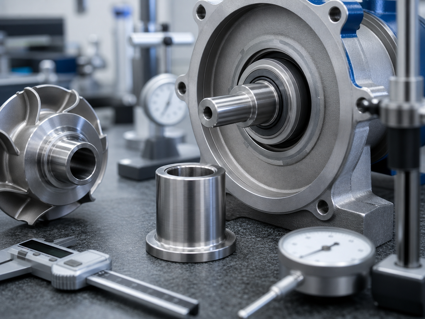
| Rotating assembly | Shaft extension, keyway, impeller hub, rotation, and axial position. | Verify with the bearing frame and impeller setting procedure. |
3. Material selection for chemical service
Material should be selected from the actual chemical duty, not from a generic “stainless steel” label. Review concentration, temperature, chloride level, solids, oxidizing conditions, and upset cases with the supplier or responsible engineer.
| Material family | Common consideration | Review before approval |
|---|---|---|
| 316 stainless steel | General process water and selected dilute chemical services. | Chlorides, temperature, pitting, and crevice corrosion. |
| Duplex stainless steel | Higher chloride resistance and strength in selected services. | Temperature limits, welding condition, and chloride concentration. |
| Alloy 20 or nickel alloys | Specific acid and aggressive chemical applications. | Acid concentration, mixed chemicals, and availability. |
| Fluoropolymer-lined construction | Useful where lining compatibility is more important than metal selection. | Temperature, vacuum, permeation, and liner condition. |
4. Installation and acceptance checklist
- Compare the received drawing with the purchase specification and nameplate.
- Check nozzle orientation, flange drilling, casing feet, and mounting dimensions.
- Confirm shaft sleeve, seal chamber, impeller, keyway, and axial setting dimensions.
- Inspect gasket faces and confirm the selected gasket and seal materials.
- Measure coupling alignment and shaft end play after assembly.
- Record material certificates, dimensional inspection records, and hydrostatic test documents when supplied.
Do not approve a replacement from a model number alone. If the pump group, seal arrangement, material, or operating duty is uncertain, send the nameplate and dimension photos for engineering review.
Request a dimensional compatibility review
Send the pump nameplate, current model, service fluid, operating temperature, material requirement, seal type, and two or three dimensional photos. ANSI Pumps Pro can then confirm the replacement scope and identify any non-drop-in conditions before quotation.
Request a pump replacement review →
Technical note: Goulds 3196 and Durco Mark III are third-party trademarks. ANSI Pumps Pro is not affiliated with or endorsed by the original equipment manufacturers. Compatibility statements should be confirmed against the specific equipment drawing and service conditions.