Hard Solids and Fibrous Debris Are Different Pumping Problems
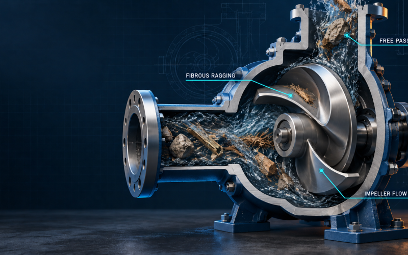
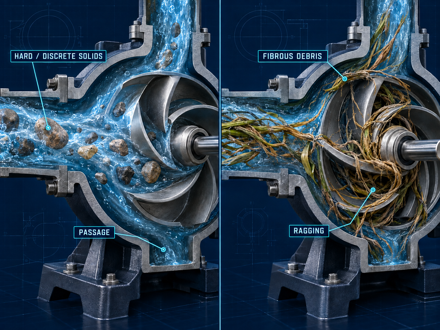
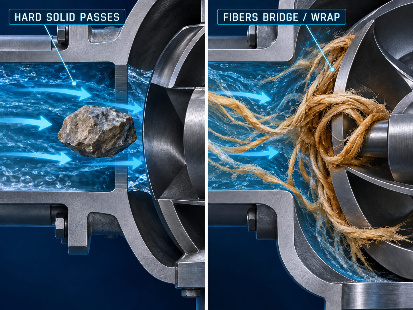
A trash or solids-handling pump should not be selected from one generic “maximum solids size.” The solids themselves first need to be classified. Hard, discrete particles such as grit, sand, gravel or mineral fragments challenge the pump through passage restriction, impact, abrasion and settling. Soft or fibrous debris such as rags, wipes, hair and stringy material can pass through a nominal opening yet still catch on leading edges, bridge across passages or wrap around rotating parts.
This distinction changes the impeller decision. A large free passage may be valuable for discrete solids, but it does not by itself prove resistance to ragging. For fibrous service, the interaction between the material, vane leading edge, casing geometry, shaft region and the entire flow path becomes just as important as the nominal throughlet size.
Hard Solids vs Fibrous Debris
Different solids create different blockage and wear mechanisms.
What “Solids Passage” Actually Means
Manufacturer literature may describe solids handling using terms such as free passage, throughlet or a stated solids-handling diameter. Those values belong to the exact pump hydraulic and should not be inferred from suction flange size, discharge flange size or a generic “trash pump” label.
For example, Gorman-Rupp publishes model-specific solids-handling data for its Super T Series. That is the correct pattern to follow: identify the exact pump and read the stated solids capability for that hydraulic. Do not convert a nominal 3-inch, 4-inch or 6-inch pump size into a universal sphere-passage rule.
Semi-Open, Channel / Non-Clog, Recessed / Vortex and Cutter Designs
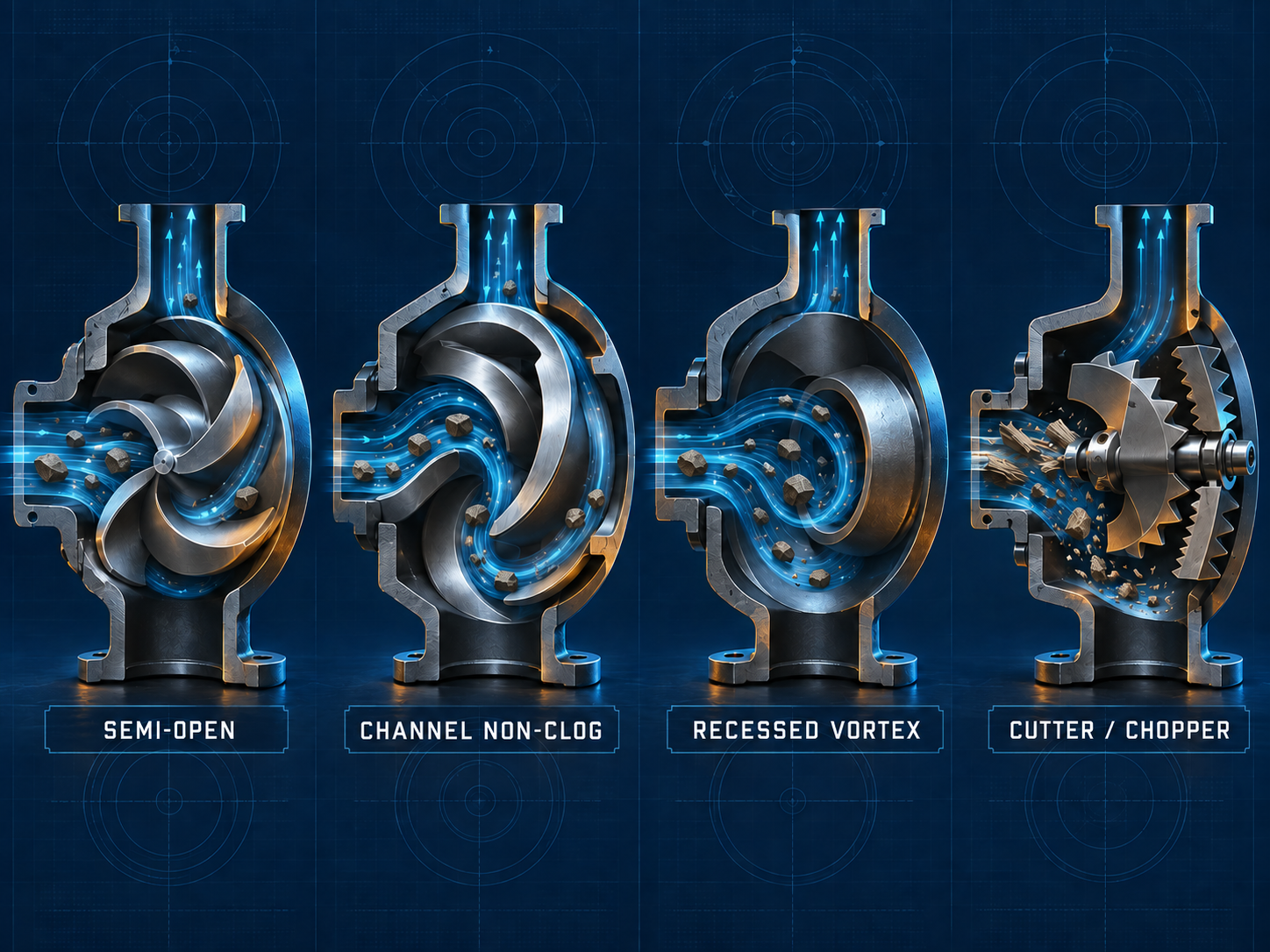
Solids-handling impellers use different strategies to move dirty liquids. A semi-open design gives direct vane interaction with the liquid and may allow accessible clearance control. Channel or non-clog designs use one or a small number of large flow passages to combine hydraulic performance with solids handling. A recessed or vortex-style impeller sits away from much of the primary flow path, reducing direct interaction between solids and vane surfaces. Cutter or chopper designs add a deliberate solids-reduction mechanism for difficult fibrous material.
These categories describe geometry and operating intent; they are not interchangeable hydraulic parts. Two impellers that both appear “semi-open” can have different eye area, vane angle, width, diameter, exit geometry and casing relationship, and therefore different head, efficiency, power and suction behavior.
Conceptual Impeller Geometry Comparison
Use this only to understand selection logic. It is not a dimensional drawing or performance comparison.
| Geometry | What it tries to solve | Main trade-off to verify |
|---|---|---|
| Semi-open | Direct pumping with accessible vane passages and design-specific running clearance | Clearance sensitivity, wear, solids interaction and actual hydraulic curve |
| Channel / non-clog | Large defined passages with useful hydraulic performance | Fibrous material can still catch at a leading edge or channel entrance |
| Recessed / vortex | Reduce direct solids contact with the rotating element and provide an open main passage | Hydraulic efficiency/head tendency, casing design and actual clogging behavior |
| Cutter / chopper | Reduce or shear difficult fibrous material before or during pumping | Cutting wear, power, maintenance and suitability for the actual debris |
For broader centrifugal-pump geometry fundamentals, use the open vs closed impeller fundamentals article. This page keeps ownership of solids-handling geometry and clogging mechanisms.
Why Free Passage Does Not Guarantee Ragging Resistance
Hard blockage and ragging are different failure modes. A discrete object can be screened against the minimum flow passage, but a long flexible solid can deform, catch on a vane leading edge, wrap around rotating geometry or accumulate gradually. The pump may continue to run while partially clogged, masking the problem as lost flow, changed power or poor sustained efficiency.
Published non-clog pump research from Xylem emphasizes the same boundary: throughlet size alone cannot characterize resistance to fibrous clogging. Recessed or vortex geometry can reduce direct interaction, but it should not be described as immune to soft-solids accumulation.
Sphere Passage vs Ragging
The two checks answer different questions.
Hydraulic Trade-Offs: Passage, Head, Efficiency and NPSHr
Increasing solids passage or reducing direct contact with the impeller changes the hydraulic geometry. Fewer or broader passages can help accommodate debris, while a deeply recessed rotating element can reduce contact between solids and vane surfaces. Those changes may also alter energy transfer, internal recirculation, head and efficiency. The direction and magnitude are pump-specific, so a generic efficiency percentage is not a defensible selection tool.
The same rule applies to NPSHr. Do not assume that one impeller category always has a fixed suction advantage or penalty. Read NPSHr from the actual selected pump curve at the required flow and speed, then compare it with the system-side NPSHa and the margin required by the project. Use the pump performance curves route for real hydraulic evidence rather than creating an illustrative H-Q curve in this article.
Do not compare conceptual impellers with invented curves
A meaningful A/B hydraulic comparison requires defined pump hydraulics, speed, impeller diameter and test basis. This article therefore explains the trade-off qualitatively and sends final selection to real curve data.
Why Clearance and Wear Change Pump Performance
Semi-open and other clearance-sensitive designs depend on the correct relationship between the impeller and adjacent casing or wear component. Abrasion, erosion, impact damage or incorrect adjustment can increase internal recirculation, change head and efficiency, and on some self-priming designs affect priming behavior. The allowable clearance and adjustment method are pump-family specific.
Do not copy a clearance from another trash pump, another impeller diameter or an ANSI process-pump platform. Use the exact manufacturer IOM, approved drawing or model-specific service procedure. The same discipline applies inside ANSI process pumps: the Goulds 3196 vs Durco Mark III impeller adjustment guide shows why even two ANSI-market platforms should not share one universal setting value.
Wear Mechanism Should Be Identified Before Changing Impeller Material
An alloy upgrade cannot correct the wrong failure mechanism. Abrasive particles can round vane edges and remove material directionally. Large hard debris may create impact damage. Corrosion can pit or selectively attack the metal. Erosion-corrosion combines hydraulic/solids damage with chemical attack. Cavitation can create surface damage that resembles other mechanisms but requires a suction and operating-point correction rather than a more expensive alloy alone.
| Observed pattern | Mechanism to investigate first | Evidence to collect |
|---|---|---|
| Rounded or thinned vane edges | Abrasive / erosive wear | Solids type, concentration, velocity, duty point, worn-part photos |
| Localized dents or broken edges | Impact from hard debris | Largest hard solids, impact marks, casing damage |
| Pitting or selective surface attack | Corrosion / chemistry | Chemical, concentration, temperature, material certification |
| Directional metal loss plus chemical attack | Erosion-corrosion | Hydraulic velocity, solids, chemistry and affected locations |
| Cavitation-like pitting near inlet region | Suction / local pressure problem | NPSHa basis, NPSHr curve, suction pressure and operating point |
For metallurgy decisions, continue to the pump impeller material selection guide and the site’s chemical resistance guide. This article does not create a second material-compatibility database or a universal “best” alloy.
Dedicated Trash / Solids-Handling Pump or ANSI Chemical-Process Pump?
A dedicated trash or wastewater solids-handling pump should be the starting category when the service is dominated by large debris, raw sewage, rags/wipes, gravel, construction waste or a required free passage. Those duties are defined first by solids handling and anti-clog behavior, not by ASME B73.1.
An ANSI chemical-process pump enters the discussion when the primary service remains a chemical-process liquid and the solids, fibres, crystals or entrained gas are secondary process features that can be handled within a verified process-pump configuration. ASME B73.1 defines the applicable horizontal end-suction chemical-process pump framework; it does not certify a trash-pump duty or prove solids-handling capability.
| Duty signal | Start with dedicated solids-handling architecture | ANSI chemical-process route may be reviewed |
|---|---|---|
| Primary problem | Large debris, raw sewage, repeated ragging, gravel or defined free passage | Chemical-process hydraulic duty with limited suspended solids/fibres as a secondary factor |
| Selection owner | Solids classification, clogging behavior, cleanout and tested solids capability | Flow/head, chemistry, materials, seal arrangement, suction and real pump curve |
| Standard | Model/project-specific solids-handling design and applicable wastewater/trash-pump requirements | ASME B73.1 where the selected horizontal chemical-process configuration is within scope |
| Commercial route | Do not force the duty into an ANSI replacement family | Proceed to ANSI family / replacement verification only after the duty fits |
If the service remains a chemical-process duty but fibres, solids or entrained gas make recessed geometry worth evaluating, continue to the CV3196 vs 3196 recessed-impeller selection guide. That page owns the CV3196 model-family decision; this page owns the broader solids-handling impeller boundary.
What to Verify Before Replacing a Solids-Handling Impeller
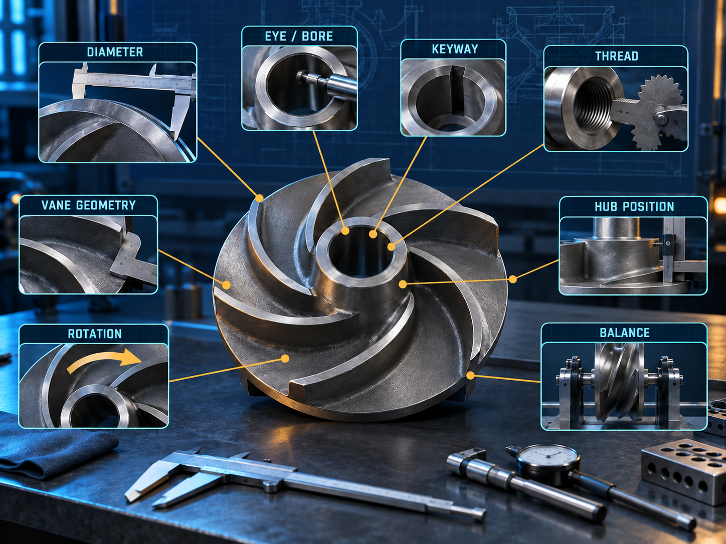
A replacement impeller is a hydraulic component, not just a casting that fits the shaft. Confirm the pump manufacturer/model/size and the original hydraulic first, then compare the impeller geometry and mechanical interfaces against the approved drawing and curve. A matching bore or outside diameter is not enough.
Replacement Impeller Verification Map
Verify both hydraulic geometry and mechanical attachment before approving a substitute part.
For a deeper inspection workflow covering dimensions, PMI and rotating-part QA, use the pump replacement parts inspection guide.
From Solids Description to a Defensible Impeller Decision
Solids-Handling Impeller Review
Move from failure mechanism to hydraulic evidence before asking for a replacement part.
Classify solids
Hard, fibrous or mixed; size, shape, concentration and abrasiveness
Locate the failure
Blockage, ragging, wear, impact, corrosion or cavitation-like damage
Choose geometry family
Semi-open, channel/non-clog, recessed/vortex or cutter/chopper candidate
Check real hydraulics
Duty point, operating range, power and NPSHr from the actual curve
Verify replacement
Drawing, interfaces, material, balance requirement and casing relationship
For an installed Goulds 3196 family pump, continue to the Goulds 3196 replacement route. For a Durco Mark III installation, use the Durco Mark III replacement route.
Trash Pump Impeller FAQ
Is a larger solids passage always better?
No. Passage must be large enough for the actual discrete solids, but increasing or changing the flow passage also changes hydraulic geometry. The selected pump still has to meet the required flow, head, efficiency, power and suction conditions on its actual curve.
Does a vortex impeller eliminate clogging?
No. Recessed/vortex geometry can reduce direct interaction between solids and the impeller, but fibrous material can still accumulate within a pump. Treat “vortex” as a design strategy, not a guarantee of clog-free operation.
Is there one standard running clearance for semi-open trash-pump impellers?
No universal value should be applied across pump families. Use the exact manufacturer IOM, approved drawing or model-specific service procedure for the installed pump and impeller configuration.
Is there one universal balance grade for a replacement impeller?
No. ISO 1940-1:2003 has been withdrawn and superseded by the ISO 21940 series. The actual balance acceptance requirement should be specified for the component, speed, pump design, service and purchaser/project requirements rather than copied from a generic article.
Can an ANSI B73.1 pump replace a dedicated trash pump?
Not from the standard designation alone. First classify the duty. Large debris, raw sewage, repeated ragging or required free passage usually point to a dedicated solids-handling architecture. An ANSI chemical-process pump should be considered only when the service remains within a verified chemical-process hydraulic and solids-handling envelope.
Technical Sources
- Xylem — Clog resistance cannot be determined by throughlet size alone.
- Xylem — Understanding sustained efficiency in non-clog pumps.
- Gorman-Rupp — model-specific Super T Series solids-handling data example.
- ASME — B73.1-2026 horizontal end-suction centrifugal pumps for chemical process.
- ISO — ISO 1940-1:2003 withdrawn status and replacement reference.
- ISO — ISO 21940-11:2016 mechanical vibration — rotor balancing procedures and tolerances.