When the Piping Pushes Back
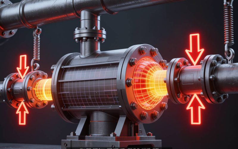
Every pump nozzle—suction and discharge—transmits forces and moments from the connected piping into the pump casing. These external loads cause casing distortion, misalignment between the pump and motor shafts, and elevated stress at the nozzle-to-casing junction. ANSI/HI 9.6.2 defines allowable nozzle loads for rotodynamic pumps, and exceeding these limits is one of the most common—and most overlooked—causes of chronic pump reliability problems.
How Excessive Nozzle Loads Damage Pumps
1. Casing Distortion and Misalignment
When the discharge pipe imposes a downward force on the pump discharge flange, the entire pump casing rotates slightly on its baseplate. Because the motor is rigidly mounted, this casing rotation misaligns the pump shaft relative to the motor shaft. A load that seems modest—say, 500 pounds of vertical force at the discharge flange—can produce 0.005-0.010 inches of shaft misalignment at the coupling. The flexible coupling absorbs some of this, but the residual misalignment increases vibration and reduces coupling and bearing life.
⚠️ Quality & Compliance Assurance
All pumps and components from ANSI Pumps Pro are manufactured to ASME B73.1 dimensional specifications. Each shipment includes certified Material Test Reports (MTRs), CMM dimensional inspection reports, and hydrostatic test certificates (1.5× MAWP). 100% dimensional interchangeability guaranteed — or your money back. Full material traceability from heat number to your receiving dock.
2. Seal Chamber Distortion
The seal chamber bore is machined into the pump casing. When the casing distorts under piping loads, the seal chamber loses its concentricity with the shaft. A seal chamber that is 0.005 inches out of round may still allow the seal to function, but 0.010-0.015 inches of distortion will cause stationary seal face distortion and leakage. This is a particularly insidious problem because the distortion is often only present when the piping is hot—the pump aligns perfectly when cold, and the seal leaks only after the system reaches operating temperature.
3. Bearing Housing Load Transfer
On many ANSI pump designs, the bearing housing bolts to the pump casing. Forces applied to the nozzles are transmitted through the casing into the bearing housing, changing the bearing alignment relative to the shaft. The result is edge-loading of the bearings—the rolling elements contact the raceway unevenly, dramatically reducing the effective L10 life.
How to Control Nozzle Loads
- Support all piping within 3 feet of pump flanges. Pipe supports should carry the weight of the piping; the pump flanges should never act as pipe supports. Use spring hangers or variable spring supports for hot piping that expands vertically during operation.
- Align piping to the pump flanges—not the other way around. Before connecting the flange bolts, verify that the pipe flange is parallel to the pump flange (within 0.015 inches across the flange face) and concentric (within 0.030 inches). If the pipe must be “pulled” to the pump, the pipe is not properly supported.
- Use expansion joints only when necessary—and anchor them properly. Expansion joints reduce nozzle loads from thermal expansion, but they introduce thrust forces (the pressure acting on the bellows area) that must be resisted by anchors. An unanchored expansion joint can increase, rather than decrease, nozzle loads.
- Perform a piping stress analysis for hot services. For pumps handling fluids above 200°F (93°C), the thermal expansion of the piping system is almost certain to impose significant nozzle loads unless the piping layout and supports are specifically designed to accommodate the expansion. A formal piping flexibility analysis per ASME B31.3 identifies and resolves these loads before the system is built.
Key Takeaways
- Excessive nozzle loads are one of the most common root causes of chronic pump misalignment and seal leakage—and they are frequently overlooked because the problem only manifests at operating temperature.
- Independent pipe supports within 3 feet of each pump flange are the single most effective measure to control nozzle loads.
- For pumps in hot service (>200°F), a piping flexibility analysis is recommended—thermal expansion can easily generate nozzle loads exceeding HI 9.6.2 allowable limits.
- If a pump aligns perfectly cold but develops vibration or seal leakage at operating temperature, suspect nozzle loads from thermal expansion of the piping.
📋 Quick RFQ — No Registration Required