
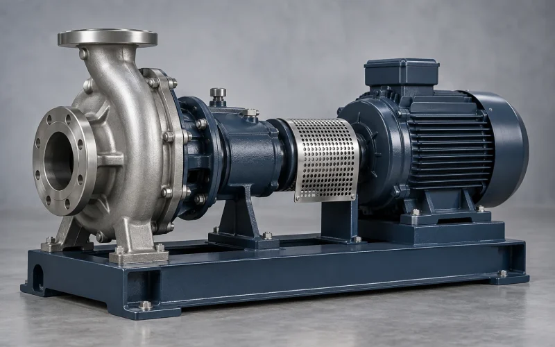
This guide provides Summit-published frame dimensions and item-number references, explains what a cross-reference can establish, and lists the information needed to verify a part before quotation. Summit item numbers below identify component positions in its 2196 manual; they are not a complete Summit-to-Goulds part-number conversion.
Summit 2196 STO, MTO, LTO and XLO frame dimensions
The following values are taken from Summit Pump’s 2196 Installation, Operation, and Maintenance Manual, Appendix G, Table 11-1. They describe specific shaft locations and frame features. Do not treat one shaft diameter as the diameter at every shaft interface.
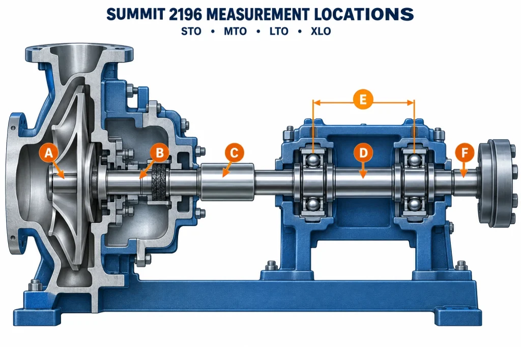
Illustrative schematic only; not an OEM drawing and not to scale. The markers show where to identify dimensions; they do not establish part interchangeability.
Measurement location key: A–F
- A — Impeller-end shaft diameter: the dimension labeled Shaft at impeller in the table.
- B — Stuffing-box shaft diameter: record the solid diameter and the diameter beneath the sleeve separately.
- C — Sleeve outside diameter: confirm the installed packing or mechanical-seal configuration.
- D — Diameter between bearings: use the value for the installed frame.
- E — Bearing span: confirm the measurement datums on the applicable frame drawing.
- F — Coupling-end shaft diameter: do not substitute the impeller-end shaft dimension.
| Frame | Shaft at impeller | Stuffing-box shaft diameter: solid / beneath sleeve | Sleeve outside diameter | Shaft at coupling |
|---|---|---|---|---|
| STO | 0.750 in (19 mm) | 1.375 / 1.125 in (35 / 29 mm) | 1.375 in (35 mm) | 0.875 in (22 mm) |
| MTO | 1.000 in (25 mm) | 1.750 / 1.500 in (45 / 38 mm) | 1.750 in (45 mm) | 1.125 in (29 mm) |
| LTO | 1.250 in (32 mm) | 2.125 / 1.875 in (54 / 48 mm) | 2.125 in (54 mm) | 1.875 in (48 mm) |
| XLO | 1.500 in (38 mm) | 2.500 / 2.000 in (64 / 51 mm) | 2.500 in (64 mm) | 2.375 in (60 mm) |
| Frame | Diameter between bearings | Bearing span | Radial bearing | Thrust bearing |
|---|---|---|---|---|
| STO | 1.500 in (38 mm) | 4.125 in (105 mm) | SKF 6207 | SKF 3306 A/C3 |
| MTO | 2.125 in (54 mm) | 6.750 in (171 mm) | SKF 6309 | SKF 3309 A/C3 |
| LTO | 2.500 in (64 mm) | 6.875 in* | SKF 6311 | SKF 7310 BECBM |
| XLO | 3.125 in (79 mm) | 9.250 in (235 mm) | SKF 6313 | SKF 3313 A/C3 |
*Summit’s manual prints 6.875 in and 164 mm for the LTO bearing span; those values do not convert to one another. The table retains the published inch value and omits the inconsistent metric conversion. Confirm the applicable drawing before using this dimension.
Reading the tables: the impeller-end shaft, shaft under the sleeve, sleeve outside diameter, bearing journals and coupling-end shaft are separate dimensions. For example, the STO coupling-end shaft is 0.875 in, while its impeller-end shaft is 0.750 in. Use the row for the installed frame and verify the construction and applicable drawing before ordering.
The published sleeve outside diameters above are for the standard 2196 frame table. Summit notes a different XLO-17 sleeve outside diameter for packing (2.75 in) and mechanical seals (2.50 in). Confirm the exact 2196 variant and seal arrangement before using a dimension to release a part.
Frame dimensions are identification aids, not a complete fit approval. They do not establish that an impeller, shaft, adapter, seal chamber or bearing housing from a different manufacturer is interchangeable.
Summit 2196 item-number reference
Summit’s manual includes separate cross-sections and parts lists for STO, MTO, LTO and XLO. The item numbers below are useful for identifying component positions in those lists. Component descriptions or item numbers can vary with frame and construction; always use the parts list for the installed model and frame.
| Summit item number | Manual description | What to confirm before ordering |
|---|---|---|
| 100 | Casing | Pump size, nozzle interfaces, material and mating impeller/cover |
| 101 | Impeller | Frame, installed diameter/trim, attachment, material and duty |
| 105 | Lantern ring | Packing arrangement and ring dimensions |
| 106 | Packing | Packing size, material and sealing arrangement |
| 107 | Packing gland | Frame, packing arrangement and stud pattern |
| 108 | Adapter (where listed) | Frame, register, bolt pattern and wet-end interface |
| 112 | Outboard bearing; description varies by frame list | Frame, bearing arrangement and the exact manual parts list |
| 122 | Shaft | Frame, solid/sleeved construction, material and all interface dimensions |
| 126 | Shaft sleeve | Shaft arrangement, inside/outside diameters, length and material |
| 134 | Bearing housing | Frame, bearing fit, frame interface and configuration |
| 168 | Inboard bearing (in applicable frame lists) | Frame and exact bearing designation |
| 184 | Stuffing-box cover | Standard/Large/Taper Bore configuration, seal dimensions and ports |
| 228 | Frame | STO/MTO/LTO/XLO, bearing arrangement and attached assembly |
| 351 | Case gasket | Pump size, joint dimensions, material and specified thickness |
Item number is not the same as an orderable part number. A cross-reference needs the manufacturer’s exact reference (including suffixes where present), the installed frame and size, and the requested material/configuration. If you only have the item number, send a photo of the applicable parts-list page or pump nameplate.
Summit 2196 to Goulds 3196: what the cross-reference establishes
ASME B73.1 addresses specified dimensional interchangeability for pumps with the same standard dimension designation, including mounting and nozzle-related interfaces. That standard does not make every internal part number or hydraulic component interchangeable across every pump family.
Summit’s published 2196 power-end brochure describes its 2196 power ends as interchangeable with existing Summit and Goulds pumps and lists STO, MTO, LTO and XLO frames. This is useful manufacturer evidence for reviewing the documented power-end assembly. The brochure does not provide a line-by-line Summit 2196-to-Goulds 3196 number conversion for every shaft, bearing, impeller, casing, adapter or seal component.
| Requested comparison | What can be stated | What must still be checked |
|---|---|---|
| Frame relationship | Identifies the frame family and narrows the parts search | Exact part number, frame revision, dimensions and configuration |
| B73.1 dimensional relationship | Supports specified installation/interface comparisons for matching standard size designations | Internal fits, seal arrangement, materials and hydraulic suitability |
| Power-end assembly | Summit publishes an interchangeability statement for its 2196 power-end assemblies | Exact frame, assembly code, retained parts, coupling and adapter interfaces |
| Individual part-number cross-reference | Associates a specific reference with a documented replacement reference | Size, drawing revision, material, trim and mating-component stack-up |
For that reason, this guide does not publish guessed Goulds 3196 part numbers or label every part “100% interchangeable.” Submit the Summit number, Goulds number, parts-list page or drawing for a specific cross-reference review. You can also use the OEM part-number cross-reference page; its listed database focuses on Goulds 3196 and Durco Mark III references, so include Summit documentation when requesting a Summit match.
Fit, seal and impeller-clearance checks
Confirm the stuffing-box cover or seal chamber
Summit lists Standard Bore, Large Bore and Taper Bore options for the 2196. Item 184 is described as the stuffing-box cover in Summit’s 2196 parts lists; do not assume that item description means every configuration uses the same seal chamber. Confirm the installed bore, chamber depth, shaft or sleeve diameter, pilot, bolt circle, flush connections and mechanical-seal working length.
Use the frame- and temperature-specific impeller clearance
Summit’s manual describes impeller clearance as the gap between the impeller vanes and casing surface. For the listed 2196 configurations at −20 to 150°F (−29 to 66°C), the starting values are:
| Frame/configuration | Published clearance |
|---|---|
| STO | 0.005 in (0.13 mm) |
| MTO / LTO | 0.008 in (0.20 mm) |
| XLO / XLO-17 | 0.015 in (0.38 mm) |
Important: Summit’s manual changes the clearance values at higher pumping temperatures. Do not apply 0.015 in to every frame or operating condition, and do not use the 2196 values for 2196R, 2196-LF or 2796. Set and recheck clearance using the applicable manual procedure before startup.
Match materials to the component and service
State the required material grade for each component when known. “Stainless” or “duplex” alone may not identify the required specification. Material selection should account for fluid composition, concentration, temperature, solids and the component’s mechanical requirements. List required certificates or inspection records in the RFQ so they can be confirmed before production.
Choose the replacement scope
| Scope | Primary checks |
|---|---|
| Individual part | Exact part reference, frame, size, dimensions, material and mating parts |
| Power end | Frame, shaft/sleeve arrangement, bearings, coupling and wet-end/adapter interfaces |
| Wet end | Casing, impeller, cover/seal configuration, shaft interface, materials and duty |
| Complete pump | Installation dimensions, operating duty, material, seal, motor and coupling requirements |
If the request concerns an installed Summit 2196 part, use the Summit 2196 replacement page to start a review. For broader power-end comparisons, see the ANSI pump power-end compatibility guide. For wet-end versus complete-pump scope, see ANSI pump wet-end replacement packages.
What to send for a Summit 2196 parts RFQ
- Complete pump size, model and STO/MTO/LTO/XLO frame from the nameplate.
- Summit item number and exact OEM part number, including suffixes, if available.
- Part description, quantity and requested delivery date.
- Material grade and documentation requirements, if specified.
- Nameplate photo, parts-list page, drawing or clear photos of the removed part and mating interface.
- For impellers, casings or complete pumps: speed, flow, head, liquid, temperature and installed impeller diameter if known.
- For a power end or seal-area part: shaft/sleeve construction, coupling details and Standard/Large/Taper Bore arrangement.
Request a Summit 2196 replacement-parts review
Frequently asked questions
Are all Summit 2196 and Goulds 3196 parts interchangeable?
No blanket part-by-part conclusion follows from the model names or B73.1 alone. Summit publishes interchangeability language for its 2196 power-end assemblies. Individual parts still require verification against the exact frame, size, number, material and configuration.
What is the difference between an item number and a part number?
An item number locates a component in a parts list or cross-section. An orderable part number identifies the specific component/configuration. Use the frame-specific parts list and the full reference when ordering.
What Summit 2196 frame dimensions should I provide?
Start with the nameplate frame and full pump size. For shaft or power-end work, also identify the relevant shaft location, sleeve construction, coupling interface and bearing arrangement. A drawing or nameplate photo helps confirm the correct data row.
Is the 0.015-inch impeller clearance used on every 2196?
No. The Summit manual lists 0.005 inch for STO, 0.008 inch for MTO/LTO and 0.015 inch for XLO/XLO-17 at −20 to 150°F. It specifies other values at higher temperatures and separate procedures for other 2196-family models.
What if I only have a worn part and no number?
Send the pump nameplate, frame and size, clear photos of the part and mating surfaces, available dimensions, material information and quantity. A part number can then be checked against the applicable list, drawing or sample.
Technical references
- Summit Pump 2196 Installation, Operation, and Maintenance Manual — frame parts lists, construction dimensions and temperature-specific impeller clearances.
- Summit Pump 2196 ANSI Power Ends brochure — published frame availability and power-end interchangeability statement.
- Summit Pump 2196 ANSI product page — model features and stuffing-box options.
- ASME B73.1 scope — specified dimensional interchangeability and installation-related requirements.