“We need this casing.”
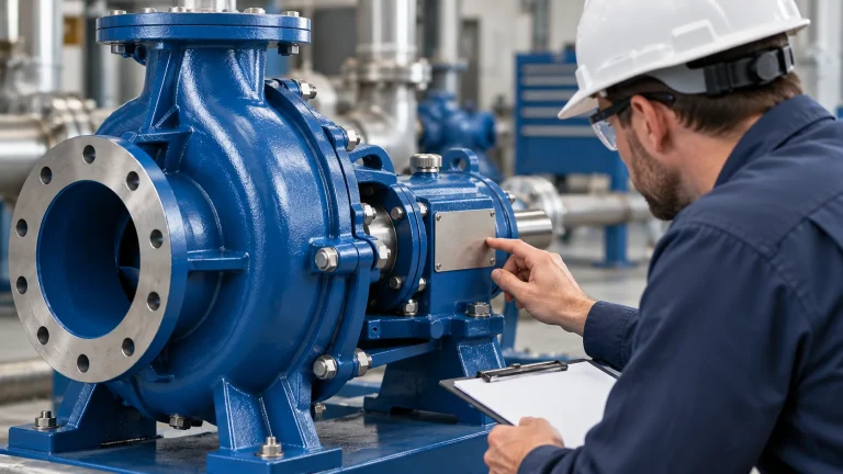
A replacement pump-casing request often begins with very little information. Sometimes the customer has a controlled drawing and part number. Sometimes they have only an old casing, a nameplate photo, a casting number and a few field measurements.
That does not make the replacement impossible—but it changes the engineering workflow. The old casing must be treated as evidence, not automatically as the original design standard. Corrosion, erosion, previous repairs, coatings, machining, pipe strain or years of service may have changed dimensions that once represented the new component.
A useful field-data package identifies the installed pump, documents the casing before measurement, measures stable interfaces from named datums, and flags dimensions that may have changed through wear, damage or repair.
Start With Identification Before Measurement
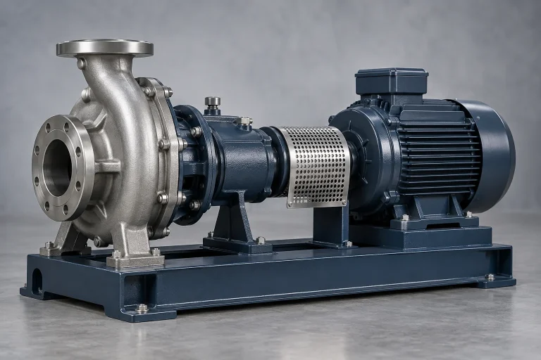
Do not begin by measuring every visible dimension. First collect whatever can identify the original configuration.
- Pump manufacturer or platform, exact model, pump size and frame/group
- Serial number or equipment tag, casting number, part number and material marking
- Rotation, nameplate, parts list, old purchase record and available drawings
- General arrangement, sectional or previous repair drawing
- Clear photographs of the complete pump
Even an incomplete casting number can be useful when combined with pump size, frame/group and photographs. If the casing has been removed, keep information that links it back to the exact installed pump.
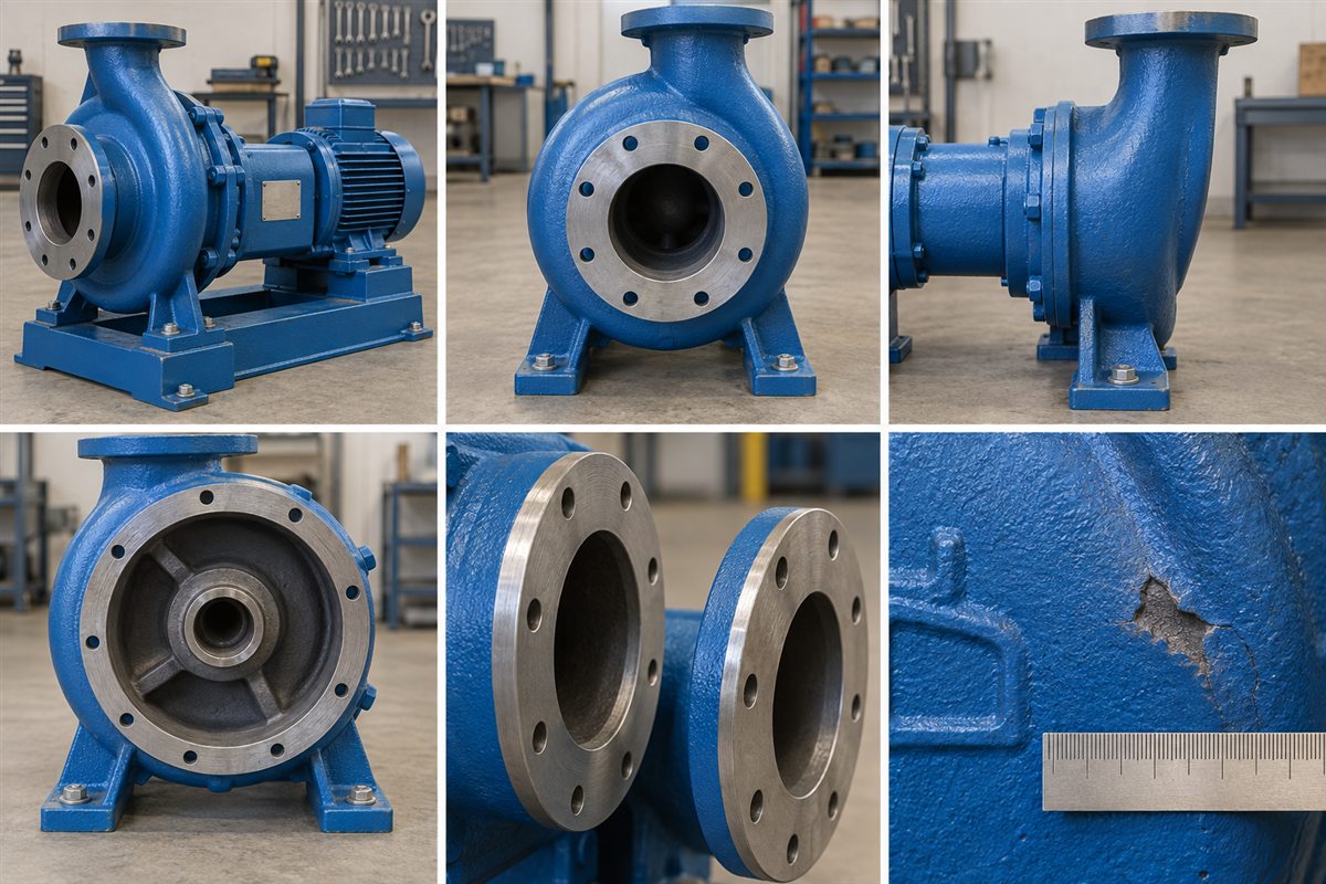
Photograph the Casing Before Cleaning or Repair
Before abrasive cleaning, grinding, welding, machining or coating removal, record the as-found condition.
- Full casing from suction and discharge sides
- Side/elevation view and rear opening or casing joint
- Suction and discharge flange faces
- Casing register/pilot and cover or seal-chamber mating surface
- Drain, vent and auxiliary connections
- Casting numbers, damaged/worn areas and previous weld repairs or coatings
Include a scale where practical. Photographs should show orientation as well as detail: a close-up of damage should not replace a full view showing where the damage sits on the casing.
Establish Datums Before Recording Dimensions
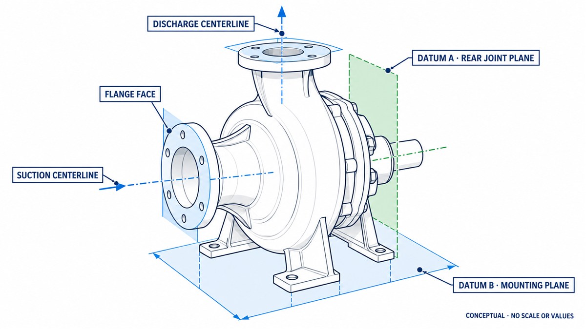
A dimension without a stated reference can be difficult to reproduce. Before measuring, define stable reference surfaces. Depending on casing design and replacement scope, useful references can include:
- Casing mounting plane or rear casing joint/gasket face
- Casing register/pilot, flange centerline or flange face
- Shaft centerline relationship derived from the assembled pump or drawing where available
- A machined bore or pilot known to be stable
Do not use heavy corrosion scale, coating thickness, damaged edges, worn sealing surfaces or distorted temporary fixtures as a design datum without engineering justification.
What to Measure on the Suction and Discharge Flanges
Record each nozzle separately. For both suction and discharge, record where applicable:
- Nominal pipe size, pressure class/rating designation and flange facing
- Outside diameter, bolt-hole count, bolt-hole diameter and bolt-circle diameter
- Flange-face thickness/position where relevant to fitment
- Orientation and centerline location relative to the selected datum
- Suction-to-discharge angular and positional relationship
Nominal flange size alone is not enough. If a face is heavily corroded, damaged or previously machined, mark that measurement as condition-dependent. Do not use pipe force or flange bolts to pull a mismatched casing into place.
Measure the Rear Casing Joint, Register and Cover Interface
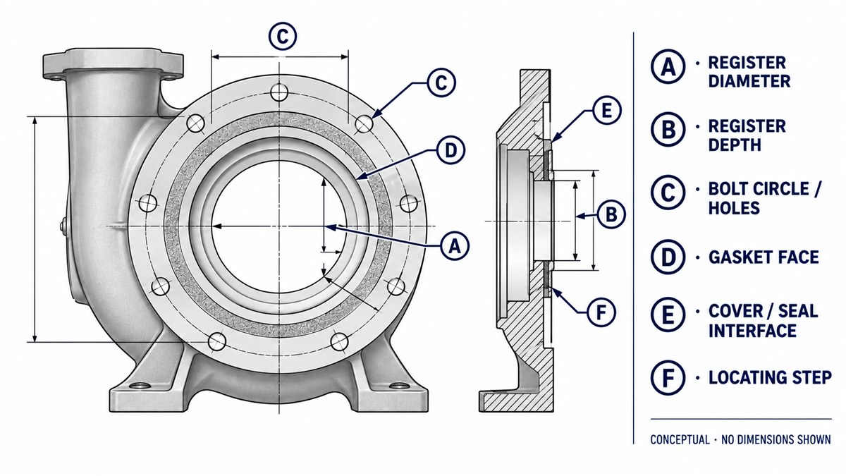
For an individual casing replacement, rear and mating interfaces may be more important than the external envelope. Depending on pump design, document:
- Register/pilot diameter and depth
- Bolt-hole count, bolt-circle and hole diameter
- Joint/gasket-face diameter and gasket groove where applicable
- Locating step, cover/seal-chamber interface and adapter/frame mating feature
- Axial depth from a named datum
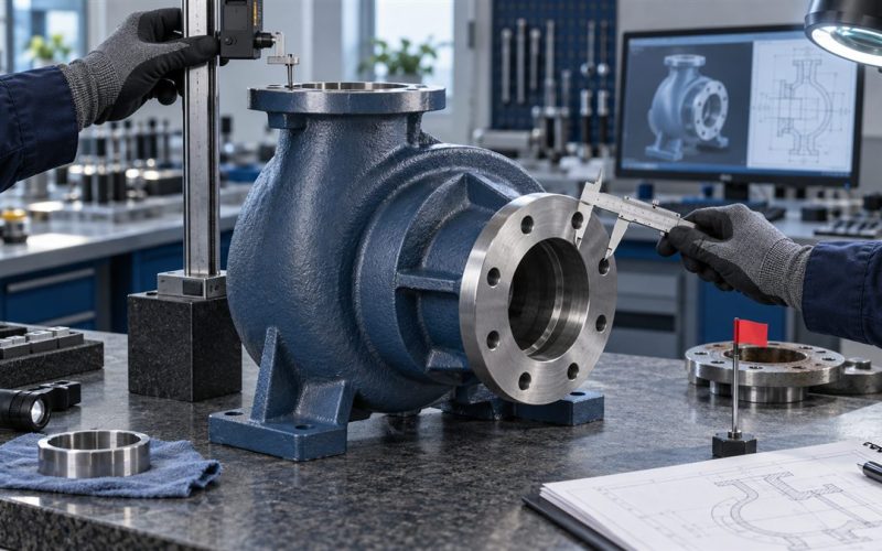
Use suitable tools for the required accuracy: caliper, micrometer, bore gauge, height gauge, pins, indicator or CMM/portable arm where appropriate. Do not assign one universal tolerance. The acceptance basis must come from the controlled drawing, approved engineering reconstruction, purchase specification, manufacturer data or inspection plan for the exact casing.
Auxiliary Connections Are Easy to Miss
Document every casing connection before ordering or reverse engineering: drain, vent, gauge, flush/recirculation, heating/cooling, priming and instrumentation ports where present.
Record size, thread/flange type, orientation, location from a named datum, whether the port is drilled/tapped or plugged, and any installed piping/tubing clearance constraint. A replacement can match major flanges and still create installation rework if small connections move.
Do Not Copy Worn Dimensions as Original Design Dimensions
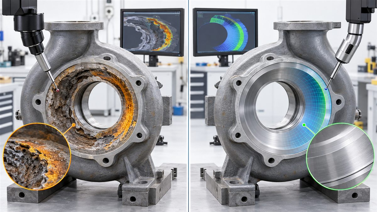
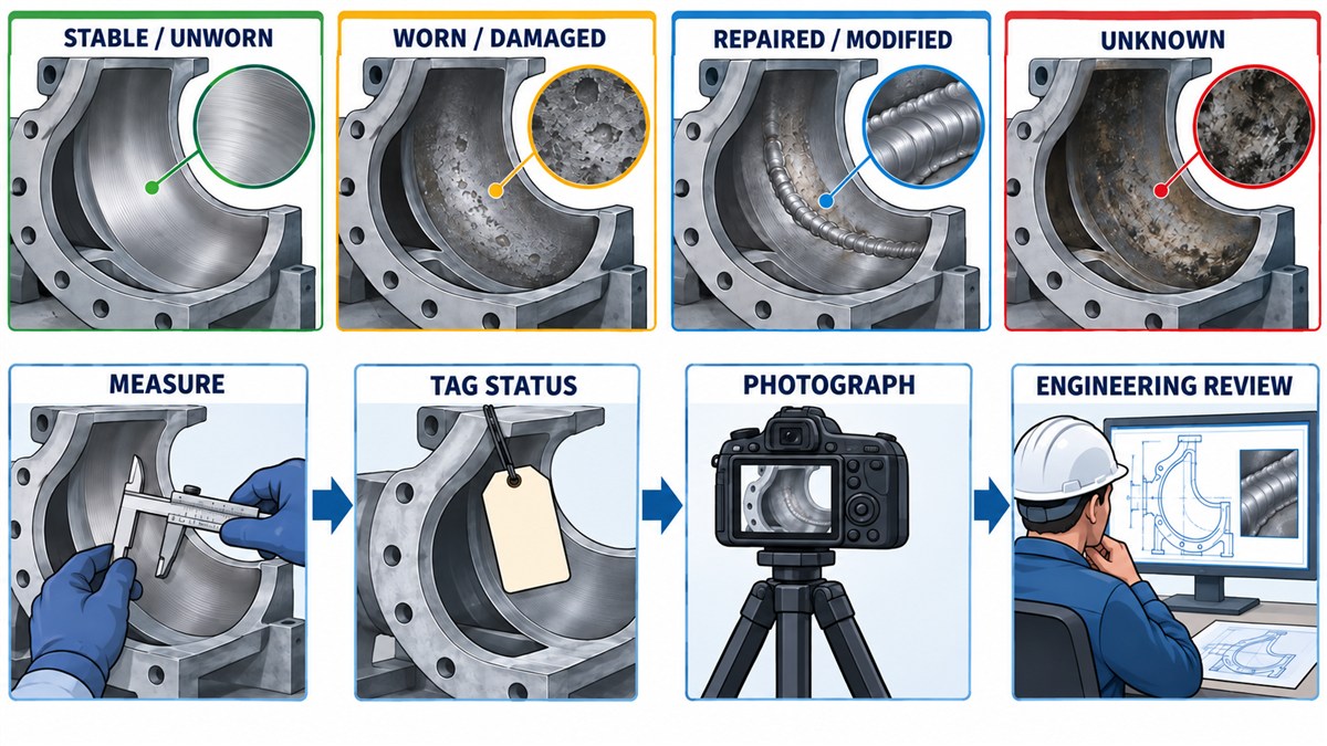
This is the most important measurement rule. An old casing may have eroded volute surfaces, a worn tongue/cutwater, corroded flange faces, thinned walls, a worn register, repaired gasket surfaces, weld buildup, repair compound, distorted feet or previous machining.
A measurement from those surfaces may accurately describe the current damaged part while inaccurately representing the original design. Tag every field measurement by evidence status:
Where symmetry, mating components, prior drawings or scan reconstruction provide better evidence, engineering can use those sources to recover the intended geometry.
What External Measurements Cannot Confirm
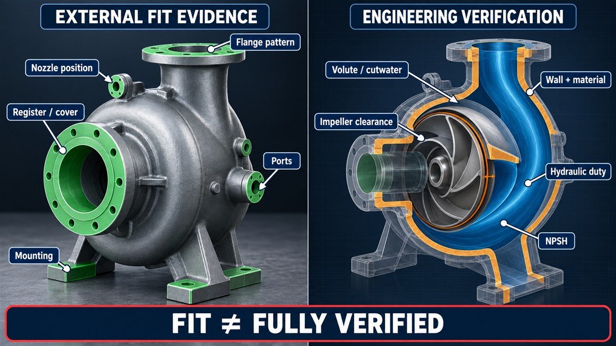
A casing can fit the piping and still be wrong internally. External measurement does not by itself establish:
- Volute cross-section, cutwater/tongue geometry or internal hydraulic passage
- Impeller-to-casing relationship, internal clearance, hydraulic performance or NPSH behavior
- Wall thickness in all pressure-boundary regions, casting integrity, material grade or pressure capability
ASME B73.1 dimensional interchangeability must not be treated as proof that internal casing geometry or individual parts from different designs are identical.
See the complete-pump installation dimensions checklist and the guide to dimensional interchangeability versus component compatibility.
For inspection after a replacement component is received, see the replacement casing and pump-parts inspection guide. For a broader replacement decision, use the ANSI pump interchangeability verification workflow.
When 3D Scanning or CMM Becomes Useful
For a simple, well-identified machined interface, conventional metrology may be enough. For a complex or obsolete casing with no usable drawing, an engineering team may use portable CMM, laser or structured-light scanning, CAD reconstruction, point-cloud comparison, or section/profile measurement.
Reverse-engineering guidance emphasizes more than reproducing visible shape. Critical characteristics include form, fit, function, interfaces/tolerances, material, loading and hydraulic function. A worn surface should not be digitized and reproduced blindly; the resulting model must be evaluated against intended function and available evidence.
Check Wall Condition Separately From Fitment
A casing is a pressure boundary. Fitment measurements do not establish that an old casing—or a repair based on it—still has adequate wall condition.
Depending on service and project requirements, evaluation may include visual inspection, wall-thickness measurement/mapping, corrosion or erosion history, NDT, material verification, engineering assessment and a controlled hydrostatic pressure test on the replacement or repaired casing where specified.
A dramatic photograph alone cannot tell whether localized attack is corrosion, a casting discontinuity, a repair artifact or another condition.
Record the Pump Duty and Impeller Information Too
Casing review is not purely dimensional. Record normal flow, normal head, minimum/maximum operating condition where known, speed/frequency, impeller diameter/trim and type, rotation, fluid, concentration, temperature, solids, specific gravity/density where relevant, and corrosion/erosion history.
The casing and impeller form a hydraulic system. A replacement casing that bolts into place but has different internal hydraulic geometry should not be approved from flange and register dimensions alone. See the site’s pump curves and engineering resources.
Field Measurement Checklist
| Area | Record | Important caution |
|---|---|---|
| Identification | Model, size, frame/group, serial/tag, casting/part number | Family name alone is not enough |
| Suction flange | Size, rating/facing, bolt pattern, centerline, face position | Flag damaged/machined flange faces |
| Discharge flange | Same as suction plus orientation | Check relationship to suction nozzle |
| Rear casing joint | Register/pilot, depth, bolt circle, gasket face | Worn register may not equal original dimension |
| Cover/seal interface | Pilot, bolt pattern, axial depth, sealing surface | Verify exact retained mating component |
| Mounting feature | Feet, pads, locating features where applicable | Check distortion/previous repair |
| Auxiliary ports | Size/type/orientation/location | Small ports can cause field rework |
| Internal condition | Wear, erosion, cutwater/tongue condition | Do not copy worn hydraulic geometry blindly |
| Wall condition | Thickness mapping/visual/NDT if required | Fitment does not establish pressure integrity |
| Material | Marking, MTR/PMI if available | Visual appearance does not prove alloy |
| Operating duty | Flow, head, speed, impeller trim | Needed for hydraulic review |
| Service | Fluid, concentration, temperature, solids | Needed for material/wear review |
What to Send for a Replacement Casing Review
| Information | Why it matters |
|---|---|
| Nameplate photo | Identifies installed pump |
| Complete pump photos | Preserves orientation/configuration |
| Casing photos from multiple sides | Shows geometry and condition |
| Casting/part number | Supports cross-reference |
| Pump size/frame/group | Narrows configuration |
| Suction/discharge measurements | Establishes piping interfaces |
| Rear register/cover-interface measurements | Establishes wet-end mating geometry |
| Auxiliary connection data | Prevents installation mismatch |
| Damage/repair photos | Identifies unreliable reference surfaces |
| Material evidence | Supports metallurgy review |
| Impeller diameter/type | Supports internal/hydraulic relationship |
| Flow/head/speed | Supports duty review |
| Fluid/temperature/solids | Supports material and wear review |
| Existing drawing/parts list, even if incomplete | Provides historical evidence |
Frequently Asked Questions
Can a replacement pump casing be made without the OEM drawing?
Sometimes, but the evidence basis must be sufficient. Identification, field measurements, mating parts, existing records and—when needed—CMM/3D scanning can support engineering reconstruction. The process should recover form, fit and function rather than blindly copying a worn component.
Which casing dimensions are most important?
They depend on the exact pump and replacement scope. Commonly important interfaces include suction/discharge flanges, nozzle position, rear casing register, cover/seal-chamber interface, gasket face, mounting features and auxiliary ports. Internal hydraulic geometry also needs separate verification.
Can I measure a corroded casing with a caliper and use those dimensions?
You can document current condition, but visibly worn or corroded surfaces should be flagged as unreliable representations of original geometry. Use stable datums, mating components, drawings, symmetry or engineering reconstruction where appropriate.
Does matching ANSI/ASME B73.1 dimensions mean the casing is interchangeable?
No. B73.1 provides defined dimensional interchangeability for specified pump-level interfaces. It does not prove identical internal volute geometry, cover registers, impeller relationships, materials or hydraulic performance for an individual casing.
Do I need 3D scanning for every replacement casing?
No. Conventional measurement may be sufficient when the part is well identified and critical interfaces are accessible and intact. Scanning/CMM becomes more useful for complex, obsolete, damaged or poorly documented geometry.
Should casing wall thickness be measured?
If corrosion, erosion or pressure-boundary condition is a concern, wall-condition evaluation may be required. The inspection method and acceptance criteria should come from the applicable engineering/design basis rather than a universal thickness number.
Technical Sources
- ASME — B73.1 Specification for Horizontal End Suction Centrifugal Pumps for Chemical Process
- Pumps & Systems — Reverse Engineering: an Alternative to Traditional Pump Repair
- Pumps & Systems — Reverse Engineering: How an Impeller Defect Was Corrected
- Pumps & Systems — Upgrade Old Refinery Pumps With Latest API Specs Materials
- Hydraulic Institute / Pumps & Systems — Casing wall-thickness FAQ
- Hydraulic Institute — Optimizing Hydrostatic Testing Procedures for Pump Casings