
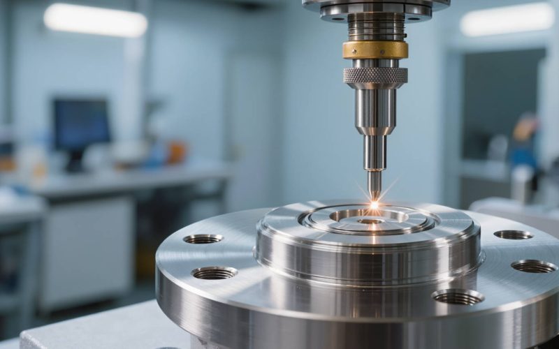
Key Takeaway: Dimensional interchangeability is only one part of compatibility. A reliable replacement must also match the pump’s hydraulic design, material specification, sealing arrangement and operating conditions. Before installing replacement parts in a Goulds 3196, Durco Mark III or another ANSI B73.1-style process pump, verify five areas: casing and piping interfaces, impeller geometry and balance, shaft/sleeve/seal interfaces, material identity and traceability, and pressure integrity.
Why Replacement Pump Parts Fail After Installation
Most compatibility problems do not become obvious while a component is sitting on an inspection bench. They appear after the pump is assembled and exposed to operating speed, pressure, temperature and piping loads. Typical symptoms include:
- Difficulty aligning the pump with existing piping
- Excessive vibration at running speed
- Recurring mechanical seal leakage
- Bearing temperature increase
- Lower-than-expected flow or head
- Cavitation or unstable operation
- Motor current above the previous operating level
- Leakage from casing joints or auxiliary connections
A flange may have the correct nominal size but an incorrect drilling pattern. An impeller may fit the shaft but have a different vane geometry. A shaft sleeve may have excessive runout. A casing supplied as stainless steel may not match the alloy specified for the process fluid.
For this reason, replacement-part approval should follow a documented verification process rather than visual inspection alone.
Information to Collect Before Inspecting Replacement Parts
Before measuring a component, confirm exactly what the replacement is intended to match. Collect as much of the following information as possible:
- Pump manufacturer and model
- Pump size and frame designation
- Serial number or equipment tag
- Original part number
- Impeller diameter
- Rotation direction
- Operating speed
- Mechanical seal arrangement
- Casing and impeller material
- Design pressure and temperature
- Process fluid and concentration
- Current pump curve or original performance data
- Drawings, dimensional reports or previous inspection records
For Goulds 3196 and Durco Mark III replacement projects, the frame group and exact pump size are especially important. Parts from two pumps in the same general product family are not automatically interchangeable. When original documentation is unavailable, send the supplier clear photographs, measured dimensions and identification markings from the existing component.
Check 1: Verify Casing and Piping Interfaces
The casing connects the pump to the process piping and establishes the position of the wet end relative to the shaft and bearing frame. A casing mismatch may create installation problems even when the suction and discharge openings appear correct.
What to Inspect
Check the following features against the original component or approved drawing:
- Suction and discharge flange size
- Flange rating and facing
- Bolt-hole quantity, diameter and bolt-circle position
- Flange orientation
- Suction and discharge centerline location
- Casing-to-frame register
- Back-cover or seal-chamber fit
- Gasket seating surfaces
- Drain, vent, flush and gauge connections
- Thread type and port orientation
- Mounting feet or support features, where applicable
A coordinate measuring machine (CMM) is useful for complex casing geometry. Calipers, bore gauges, height gauges, pin gauges and dial indicators can also be used when a validated inspection method is available.
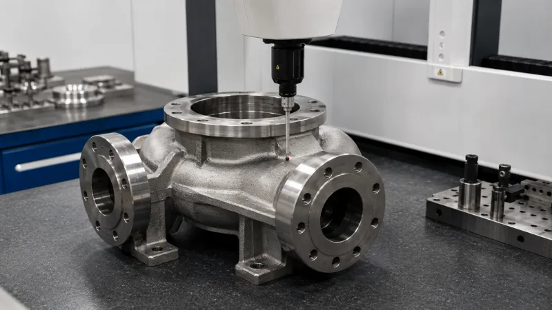
CMM inspection verifies critical casing dimensions, flange positions, bolt circles and frame interfaces before assembly.
Why This Matters
Incorrect flange drilling or nozzle position can force installers to pull the piping into alignment. This introduces external loads into the pump casing and may contribute to:
- Coupling misalignment
- Casing distortion
- Gasket leakage
- Seal face movement
- Higher vibration
- Cracking around the nozzle or casing neck
The pump should fit the system without using piping force to compensate for dimensional differences.
Recommended Inspection Record
Record the nominal dimension, measured dimension, drawing tolerance, inspection tool and inspection result. Do not apply one universal tolerance to every pump size. Acceptance limits should come from the approved drawing, applicable standard, OEM documentation or a mutually agreed inspection plan.
Check 2: Confirm Impeller Geometry, Fit and Balance
The impeller is not only a rotating spare part. It is the primary hydraulic component that determines the relationship between flow, head, efficiency and required net positive suction head. Two impellers may share the same outside diameter and shaft bore while producing different performance.
What to Inspect
- Impeller type
- Rotation direction
- Outside diameter
- Inlet-eye diameter
- Vane number and profile
- Vane exit geometry
- Hub length
- Bore diameter
- Keyway dimensions
- Thread direction where a threaded attachment is used
- Axial position in the casing
- Front and rear clearances
- Runout
- Balance condition
For reverse-vane impellers, the rear-vane geometry and impeller setting method must also match the intended pump design.
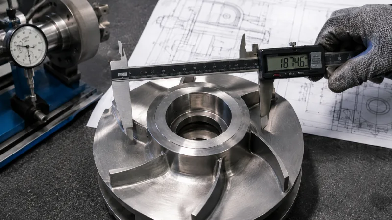
Impeller diameter, inlet eye, hub and vane geometry are checked against the approved drawing before installation.
Dynamic Balance
The required balance grade should be specified according to impeller mass, operating speed, service severity, pump design, and purchaser or project specification. Ask the supplier for a balance report that identifies the component, balancing standard, speed or calculation basis, acceptance criterion and final result.
The relevant balancing reference is ISO 21940, including the applicable part of that standard. The actual acceptance grade should be selected for the pump and service rather than copied from a generic article.
Why This Matters
An incorrect or poorly balanced impeller may cause vibration at rotational frequency, accelerated bearing wear, mechanical seal instability, shaft deflection, motor overload, reduced flow or head, increased NPSH requirement, or cavitation near the impeller inlet. For critical duties, compare the replacement impeller with the approved pump curve or test data.
Check 3: Inspect the Shaft, Sleeve and Seal Interfaces
Mechanical seal problems are often blamed on the seal itself. In many cases, the real cause is excessive runout, an incorrect sleeve dimension or a mismatch between the seal and the seal chamber.
What to Inspect
- Shaft diameter at bearing and seal locations
- Shaft straightness
- Shaft shoulder position
- Sleeve inside and outside diameter
- Sleeve length
- Sleeve surface finish
- Sleeve and shaft runout
- Keyway dimensions
- Threads and locking features
- Seal chamber bore
- Seal chamber depth
- Gland pilot
- Gland bolt pattern
- Gasket or O-ring interfaces
- Impeller-to-sleeve and sleeve-to-shaft fits
Measurements should be taken from clean, undamaged reference surfaces. A worn original sleeve should not automatically be treated as the nominal dimension.
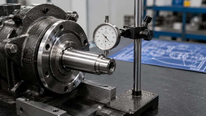
Shaft and sleeve runout are measured to confirm concentricity and mechanical seal compatibility.
Seal Chamber Compatibility
Confirm the installed seal model or required seal envelope before approving the replacement chamber. A standard bore, large bore and tapered bore seal chamber can have different internal geometry, circulation characteristics and available space. The inspection should verify that the seal can be installed without uncontrolled shimming, re-machining or field modification.
Why This Matters
Excessive shaft or sleeve runout can produce uneven seal-face loading. Incorrect chamber depth or gland position can change seal compression and operating position. Possible results include leakage immediately after startup, rapid seal-face wear, damaged secondary seals, heat generation, fretting, and shortened bearing and seal life. For a complete wet-end replacement, check the combined tolerance stack rather than approving each component independently.
Check 4: Verify Material Identity and Traceability
Correct dimensions cannot compensate for the wrong material. Chemical process pumps may handle acids, alkalis, solvents, chlorides, slurries or high-temperature fluids. A substituted or incorrectly identified alloy can experience rapid corrosion even when the component appears visually acceptable.
Documents to Request
- Material test report (MTR)
- Heat number
- Casting identification
- Chemical composition
- Mechanical properties
- Heat-treatment record
- Positive material identification (PMI) report
- Nondestructive examination report
- Repair-welding record, when applicable
- Third-party inspection report, when required
The heat number marked on the component should correspond with the supplied material documentation.
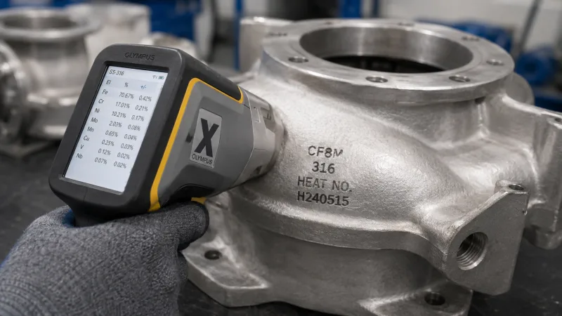
Positive material identification helps confirm alloy grade and heat-number traceability for chemical pump components.
PMI Limitations
Portable X-ray fluorescence (XRF) equipment can help verify many alloying elements in stainless steels and nickel alloys. However, some handheld XRF instruments are not suitable for accurately measuring light elements such as carbon. When grade differentiation depends on carbon or another difficult-to-measure element, use an appropriate laboratory or optical-emission method. PMI should support—not replace—material traceability and the approved material specification.
Why This Matters
Incorrect materials may lead to pitting, crevice corrosion, stress-corrosion cracking, erosion-corrosion, intergranular attack, loss of casing wall thickness, contamination of the pumped product, or pressure-boundary failure. For a detailed guide on alloy selection, review the ANSI pump material selection guide.
Check 5: Confirm Pressure Integrity and Hydraulic Suitability
After dimensional and material checks, the pressure-containing parts must be inspected and tested according to the approved quality plan.
Hydrostatic Testing
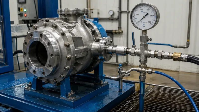
A hydrostatic test can help identify casting porosity, leakage through repaired areas, defects around drain or vent ports, leakage at pressure-containing joints, and weaknesses that are not visible during dimensional inspection. The test pressure, holding time, test medium and acceptance criteria should follow the applicable design requirement, customer specification or approved inspection procedure.
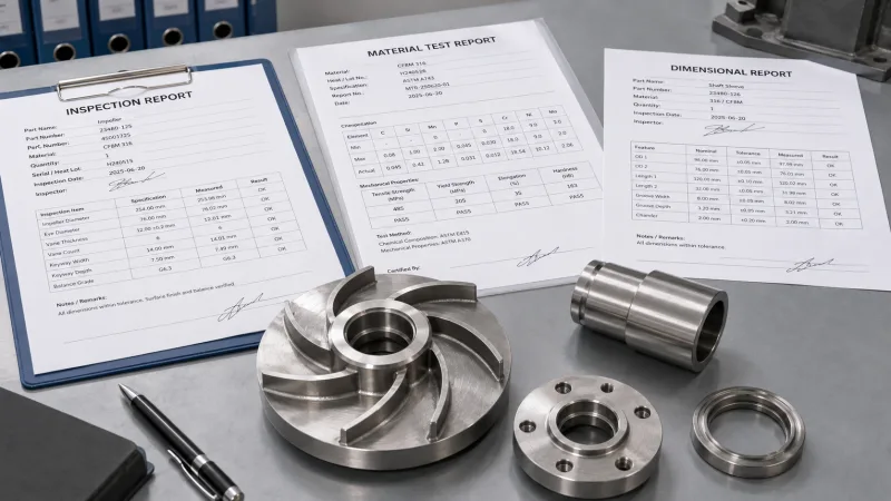
The test certificate should identify the component or serial number, material, test pressure, holding time, test medium, test date, result and inspector.
Hydrostatic testing verifies pressure integrity before the pump casing is approved for shipment.
Hydraulic Suitability
A casing can pass a pressure test and still be hydraulically unsuitable. For replacement impellers or complete wet ends, review impeller diameter, rated flow and head, operating speed, efficiency, power requirement, NPSH available and required, expected operating point, minimum continuous stable flow, and process-fluid properties. When the replacement differs from the original hydraulic design, request a performance curve or test information rather than relying only on dimensional interchangeability.
Why This Matters
An unverified wet end may produce inadequate plant flow, excessive discharge pressure, cavitation, unstable operation, motor overload, high recirculation, or reduced efficiency.
Incoming Inspection Checklist
Before releasing aftermarket pump parts for assembly, confirm that your inspection file contains the following:
| Inspection Item | Evidence to Retain |
|---|---|
| Correct pump model and size | Purchase order, equipment tag or approved drawing |
| Part identification | Part number, casting mark or cross-reference |
| Critical dimensions | Dimensional inspection report |
| Impeller condition | Diameter, runout and balance report |
| Seal interface | Chamber and sleeve inspection results |
| Material identity | MTR and heat-number traceability |
| PMI, when required | PMI report linked to the component |
| Pressure integrity | Hydrostatic test certificate |
| Hydraulic suitability | Approved curve or engineering confirmation |
| Final release | Inspection sign-off and photographs |
This documentation also makes future maintenance easier. When the same pump is overhauled again, the maintenance team has a verified reference instead of starting from zero.
Questions to Ask an Aftermarket Pump Parts Supplier
Before placing an order, ask the supplier:
- Which exact pump size, frame and part number is this component designed to replace?
- Which dimensions are inspected before shipment?
- Can you provide a dimensional inspection report?
- Is the impeller supplied with a balance report?
- Can the casting heat number be traced to the MTR?
- Is PMI available for alloy parts?
- What pressure test is performed on the casing?
- Can you confirm seal chamber and shaft-sleeve interfaces?
- Is a pump curve or hydraulic comparison available?
- What is the process for handling a documented nonconformance?
A professional supplier should be able to explain the verification method, not simply state that a component is “100% compatible.”
How ANSI Pumps Pro Verifies Replacement Parts
ANSI Pumps Pro supplies replacement wet-end parts and pump components for ANSI B73.1-style process pumps. Depending on the component and order requirements, available quality documentation may include dimensional inspection reports, CMM measurement records, material test reports, heat-number traceability, PMI reports, impeller balance reports, hydrostatic test certificates, inspection photographs, and third-party inspection upon request.
Compatibility is reviewed against the pump model, size, frame, material, impeller diameter, sealing arrangement and available reference documentation. Because pump configurations vary, final suitability should always be confirmed for the specific equipment and operating service. Learn more about our ANSI pump replacement parts service.
Dimensional reports, material certificates and inspection records provide traceability for replacement pump components.
Frequently Asked Questions
Are all ANSI B73.1 pump parts interchangeable?
No. ANSI B73.1 establishes important dimensional and design requirements for horizontal end-suction chemical process pumps, but it does not make every component from every manufacturer interchangeable. Interchangeability must be confirmed for the specific pump model, size, frame and component.
Is matching the OEM part number enough?
A part number is a useful starting point, but it should be supported by pump model, size, frame, material and impeller information. Equipment may have been modified during previous repairs, and the installed component may differ from the original configuration. Review the OEM part-number cross-reference for guidance.
How can I verify a Goulds 3196 replacement impeller?
Confirm the pump size and frame, impeller type, rotation, diameter, bore or thread, keyway, vane geometry, axial setting and balance condition. For critical service, compare the proposed impeller with the original hydraulic curve or approved test information. Browse our Goulds 3196 replacement components for reference.
What documents should be supplied with an alloy casing?
Depending on the order, documentation may include an MTR, heat number, PMI report, heat-treatment information, nondestructive examination results, dimensional inspection report and hydrostatic test certificate.
Can a replacement seal chamber be installed without modification?
It can be installed without modification only when the chamber bore, depth, gland pilot, bolt pattern, shaft or sleeve dimensions and seal envelope match the intended configuration. Confirm the mechanical seal model before machining or ordering the chamber.
Should every replacement part be measured by CMM?
Not necessarily. CMM inspection is most valuable for complex geometry and critical interfaces. Simpler parts may be verified with calibrated gauges and conventional inspection tools. The inspection method should be appropriate for the risk and required tolerance.
Final Recommendation
Do not approve an aftermarket ANSI pump component based only on appearance, nominal size or a general compatibility claim. Before installation, confirm mechanical interfaces, impeller geometry and balance, shaft and seal dimensions, material traceability, pressure integrity, and hydraulic suitability. A documented verification process reduces rework, protects the maintenance schedule and gives the plant a repeatable basis for approving replacement parts.
📋 Request a Compatibility Review
Send us the following information. Our engineering team will review and advise on additional dimensions or documents needed before quotation.
ANSI Pumps Pro — Replacement parts designed for dimensional interchangeability with Goulds 3196, Durco Mark III and other ANSI B73.1 process pumps. Available in 316SS, CD4MCuN, Hastelloy C-276, Alloy 20 and Titanium with full EN 10204 3.1 MTR documentation. Documentation available depending on order requirements. Request a compatibility review →