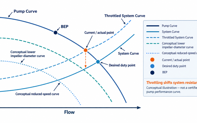
Start with the pump’s actual duty—not motor size or symptoms alone. Record minimum, normal and maximum flow where possible, then compare measured head with the approved pump curve and the system curve before choosing a corrective action.
This guide shows what to measure, how to confirm the mismatch and when to evaluate impeller trimming, variable speed, system changes or pump reselection.
PUMP RELIABILITY · DUTY REVIEW
Quick Check: Does the Pump Need an Oversizing Review?
On small screens, scroll this table horizontally to view all columns.
| What you see | What it may indicate | Verify first |
|---|---|---|
| Control valve remains heavily throttled | Excess available head or a control mismatch | Actual flow, TDH, valve position and system curve |
| Bypass stays open during normal operation | Excess capacity or a required minimum-flow function | Useful flow, bypass flow and minimum-flow requirement |
| Operating point sits far from BEP | Hydraulic duty may not match the selected pump | Approved pump curve, actual duty and permitted operating range |
| Repeated vibration, seal or bearing problems | Off-design hydraulic loading may be contributing | Vibration, alignment, suction condition and operating point |
| Pump frequently cycles on and off | Installed capacity may exceed normal process demand | Control logic, tank level, duty profile and required flow range |
Important: These are warning signs, not proof. Throttling, bypass flow, vibration or cycling can have other causes. Confirm the hydraulic duty before changing the pump.
What Is an Oversized Centrifugal Pump?
An oversized centrifugal pump is a pump whose available hydraulic capacity is materially greater than the process requires across the relevant operating range. The practical question is not whether the pump or motor looks large, but where the installed pump actually operates relative to the required duty, pump curve and system curve.
Oversizing can result from accumulated design margins, a process change, changed piping or a duty estimate that no longer represents normal operation. A pump may be technically operable but still be a poor hydraulic or reliability match. Motor size alone does not prove that a pump is oversized.
Five Warning Signs Your Pump May Be Oversized
1. The discharge control valve stays heavily throttled
Throttling can be a legitimate control method. Persistent restrictive operation deserves a review when the valve is routinely dissipating excess head during normal duty. Measure flow, head and valve position before deciding that the pump is too large.
2. A bypass or recirculation line remains open
A bypass may protect minimum flow or serve a process function. Continuous recirculation can also be a permanent workaround for excess capacity. Distinguish required protection from a bypass that is compensating for a mismatched selection.
3. The operating point is far from BEP
BEP is a reference point, not the only valid operating point. Compare the actual duty with the approved curve and the manufacturer-approved preferred or allowable operating region (POR/AOR), without applying a universal percentage threshold.
4. Available head or flow is consistently higher than the process needs
If the system repeatedly restricts the pump to reach the required flow, compare the real demand with the selected curve. Check whether static head, friction, valve losses, branch operation or process conditions have changed.
5. Reliability symptoms keep returning
Noise, vibration, seal failures, bearing problems, heating or motor loading may accompany off-design operation. These symptoms are not unique to oversizing. Check alignment, suction conditions, piping, bearings, seals and the operating point together. Hydraulic radial loading can rise as flow moves away from BEP on some designs, but its magnitude depends on pump geometry and operating condition; do not infer a universal force multiplier from symptoms alone. See the Hydraulic Institute overview of radial-thrust factors.
Confirm Oversizing Before Modifying the Pump
- Confirm pump identity. Collect the manufacturer/model or installed family, pump size, frame/group where applicable, RPM, existing impeller diameter, nameplate and approved or available curve.
- Measure actual flow. Record minimum, normal and maximum flow where possible.
- Determine actual head / TDH. Use suction and discharge conditions plus elevation and loss basis where applicable. Use the pump calculators to calculate or organize TDH and system data.
- Build or verify the system curve. Include static head, pipe friction, valves and fittings, control position, changing levels and parallel branches where relevant.
- Plot the actual operating point. Compare actual Q/H with the approved pump curve, current impeller and speed.
- Review BEP, POR/AOR and operating constraints. Check the approved region, NPSH, motor load, vibration, stability and minimum flow where applicable.
- Review more than one operating condition. If tank level, process demand, valve position or speed changes materially, one operating point may not represent the real duty profile.
Pump Curve vs System Curve: What Oversizing Looks Like
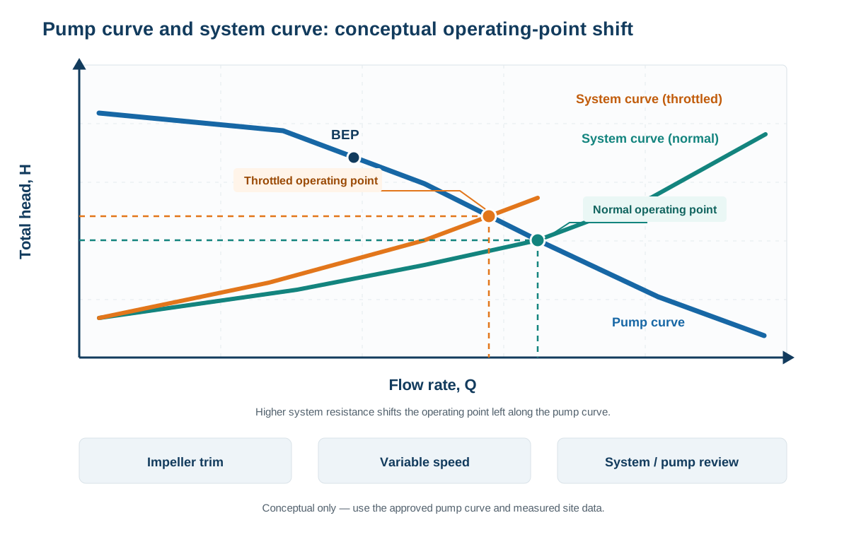
The intersection of the pump curve and system curve defines the operating point. Throttling changes system resistance; it does not change the pump’s inherent curve. Impeller trim changes the pump curve, a speed change changes pump performance, and reselection changes the hydraulic match. For a step-by-step curve reading, see our centrifugal pump curve guide.
The diagram is intentionally conceptual and contains no certified performance values. Use the approved curve for the installed pump and measured site data for a real selection decision.
What Continuous Throttling Can Tell You
Throttling is not automatically wrong. Persistent throttling may mean excess head is being dissipated, while operation at lower flow can increase internal recirculation or hydraulic loading depending on the design. Quantify the system before recommending a fix; do not claim a fixed energy penalty.
Optional valve-loss power estimate
Q = flow rate; ΔPvalve = valve pressure drop; ηpump and ηmotor = pump and motor efficiencies as decimals.
Use flow and pressure drop from the same operating condition. This estimates electrical input associated with dissipating head across the valve under those assumptions; it is not a guaranteed recoverable saving. Include drive losses where applicable, and estimate annual energy from the actual operating profile, runtime and control response.
Corrective Option 1: Impeller Trimming
Impeller trimming may be a candidate when duty is relatively stable, excess head is persistent, and the manufacturer or design geometry permits the trim. Review the revised curve, diameter, efficiency, power, NPSH, balance, clearances, vibration and minimum/normal/maximum duty.
Do not define the final trim diameter from a simple proportional calculation alone. Confirm it against the applicable hydraulic curve and the manufacturer’s or designer’s limits.
Affinity relationships are a screening estimate
For a limited impeller-diameter change, simplified estimates are:
Q₁, Q₂ = flow before and after trim; H₁, H₂ = head before and after trim; P₁, P₂ = absorbed power before and after trim; D₁, D₂ = impeller diameters before and after trim.
These relationships are screening estimates; they do not establish the final trimmed curve, efficiency or permitted diameter range. Use the HI pump-curve guidance and verify the proposed trim against the applicable manufacturer or validated replacement curve before machining.
Corrective Option 2: Variable Speed / VFD
A VFD may suit a process with materially changing demand when the pump, motor and control system are compatible with variable-speed operation. Review minimum speed/frequency, motor cooling, torque, resonance or critical vibration, NPSH, seal and lubrication considerations, control stability and minimum flow.
A VFD cannot correct a damaged impeller, poor suction design, blocked piping or another root cause that has been mistaken for oversizing.
When static head is a substantial part of total system head, reducing speed may lower pump head below the system requirement before the desired flow is reached. Compare speed-specific pump curves with the actual system curve—including static head—and verify stable minimum flow and control limits before selecting a minimum speed.
Corrective Option 3: System and Control Changes
Review control-valve strategy, unnecessary pressure drop, permanent bypass flow, changed piping, branch operation, process demand, tank-level control and instrumentation errors. Not every case needs a replacement pump; system correction may be the safer first action.
Corrective Option 4: Reselect or Replace the Pump
Consider a new hydraulic selection when the process duty permanently changed, the required impeller solution is outside a suitable range, the pump cannot operate reliably across required conditions, power or NPSH constraints remain unresolved, the installed unit is approaching major overhaul, or system correction does not produce an acceptable operating range.
Corrective-Action Decision Matrix
On small screens, scroll this table horizontally to view all columns.
| Operating condition | Impeller trim | VFD | System/control review | Pump reselection/replacement |
|---|---|---|---|---|
| Stable duty with persistent excess head | Strong candidate if the hydraulic range permits | Often unnecessary | Verify valve/system losses | Compare if trim is outside a suitable range |
| Wide variable-flow demand | May optimize only one condition | Strong candidate if the equipment supports it | Verify control strategy | Evaluate if the required range cannot be covered |
| Continuous bypass | Possible | Possible | High priority | Evaluate hydraulic sizing if excess capacity remains |
| Operation outside an acceptable region | Do not trim before root-cause review | Do not use VFD as a substitute for diagnosis | Required | Evaluate if the installed selection remains unsuitable |
| Existing pump requires major overhaul | Compare lifecycle value | Compare lifecycle value | Verify system duty | Strong reason to review a correctly sized replacement |
| Process duty has permanently changed | Recalculate | Recalculate | Recalculate | Often worth evaluating |
The table is a screening tool, not a final selection. Confirm the specific pump curve, operating range, NPSH, motor, materials, seal arrangement and system conditions.
Replacing an Oversized ANSI B73.1 Process Pump
If the installed unit is an ANSI/ASME B73.1 process pump, an oversizing review is also an opportunity to correct the hydraulic selection while checking the installation interfaces required for replacement. ASME describes interchangeability for pumps with the same standard dimension designation across defined installation interfaces; that does not by itself verify the replacement’s hydraulic duty, internal mechanical fit, materials or service suitability. A replacement should not be selected from the family name alone. Confirm the actual duty and installed pump configuration before quotation. See the ASME B73.1 standard scope and our B73.1 dimensional-interchangeability guide.
- Existing model/family
- Pump size and frame/group
- Suction/discharge interfaces
- Base or mounting arrangement where relevant
- Current impeller diameter
- Shaft/seal arrangement
- Wet-end materials
- Motor/speed
- Required Q/H range and NPSH conditions
- Approved performance curve
Replacing an Existing Goulds 3196 or Durco Mark III?
For an installed Goulds 3196 or Durco Mark III, confirm the exact size, frame or group, hydraulic duty, impeller, seal arrangement, materials, shaft/interface details and performance curve. The model-family name by itself does not prove that a proposed pump is the correct hydraulic or dimensional replacement. See the Goulds 3196 replacement review and Durco Mark III replacement review when the configuration review calls for it.
What Data Should You Send for an Oversized-Pump Review?
Pump identity
- Model/family, pump size and frame/group
- Nameplate photo and current pump curve
- Impeller diameter and speed/RPM
Actual operating duty
- Minimum, normal and maximum flow
- Suction pressure, discharge pressure and TDH if known
- Valve position and bypass condition
Fluid
- Liquid/service, density or specific gravity
- Viscosity, temperature and vapor pressure if known
- Solids if applicable
Equipment and condition
- Motor power and VFD speed range if applicable
- Vibration observations or data
- Seal/bearing failure history and recent piping/process changes
If replacement is being considered
- Materials, seal arrangement and dimensions/drawing
- Required supply scope: complete pump, bare pump, wet end or other
Not Sure Whether the Pump Is Oversized?
Send the installed pump model, curve and actual operating data. We can review what should be verified before you consider an impeller trim, speed change, system correction or ANSI replacement pump.
Review My Pump Operating Point Start ANSI Pump Selection
Start with the data you already have — a nameplate, pump curve or current Q/H is enough for an initial review.
From Oversizing Diagnosis to a Replacement RFQ
- 01 — MeasureActual flow · head · RPM · valve position
- 02 — ComparePump curve · system curve · BEP / operating region
- 03 — DecideTrim · VFD · system correction · reselection
- 04 — VerifyHydraulics · NPSH · motor · materials · seal · interfaces
- 05 — RFQSubmit the installed pump information and required duty
Frequently Asked Questions
How do I know if my centrifugal pump is oversized?
Start by comparing the actual flow and head with the approved pump curve and the system curve. Persistent throttling, bypass flow or operation far from the preferred region can justify a review, but none of those symptoms proves oversizing by itself.
Does a throttled discharge valve mean the pump is oversized?
Not necessarily. Throttling may be part of the intended control strategy. If the valve remains heavily restricted during normal operation, compare the actual duty with the pump and system curves to determine whether excess head or a control mismatch exists.
Can an oversized pump cause vibration, seal or bearing problems?
Operation away from the intended hydraulic region can contribute to unstable flow, hydraulic loads, vibration and reliability problems, but these symptoms also have other mechanical and system causes. Check alignment, suction conditions, bearings, seals, piping and the operating point before assigning the cause to oversizing.
Can a VFD fix an oversized pump?
A VFD can be a useful corrective option when the process requires variable flow and the pump, motor and control system are suitable for variable-speed operation. It does not replace a root-cause review of suction problems, damaged components, incorrect instrumentation or other system faults.
Should I trim the impeller or replace the pump?
Impeller trimming may suit a stable duty when the required diameter stays within an acceptable hydraulic range. Replacement or reselection becomes more relevant when the process duty has changed substantially, the required trim is unsuitable, or the installed pump cannot cover the required operating range reliably.
How does pump oversizing affect BEP and efficiency?
Oversizing can force the actual operating point away from the region for which the pump was selected, especially when the system relies on throttling or bypass to control excess capacity. Review the actual operating point against the approved curve, BEP and permitted operating region rather than using BEP as a single universal pass/fail point.
What data do I need to resize or replace an ANSI pump?
Provide the installed model and size, pump curve, current impeller diameter, RPM, minimum/normal/maximum flow, suction and discharge conditions, fluid data, motor information and the required replacement scope. For a drop-in or interchangeable review, also provide the frame/group, materials, seal and dimensional/interface information.
Technical References
- U.S. Department of Energy pump-system resources for industrial system assessment and efficiency guidance.
- Hydraulic Institute ANSI/HI 9.6.3 for POR/AOR definitions and operating-region factors.
- Hydraulic Institute pump curves and affinity relationships for curve interpretation and preliminary estimates.
- Hydraulic Institute guidance on impeller trimming; final limits must come from the applicable pump curve and manufacturer/designer.
- ASME B73.1 scope and dimensional-interchangeability statement.
- The applicable manufacturer-approved or certified curve for the actual installed pump and the project’s operating requirements.