

01 · Start with a repeatable reading
What to do first when a pump vibrates
If the reading reaches a plant alarm or trip condition, follow the site operating and safety procedures first. Do not change a protection setting or approach a moving coupling to take a measurement. When it is safe to measure, confirm the instrument, sensor mounting, units, speed, and exact measurement location.
02 · Define the measurement
Where to measure and what to record
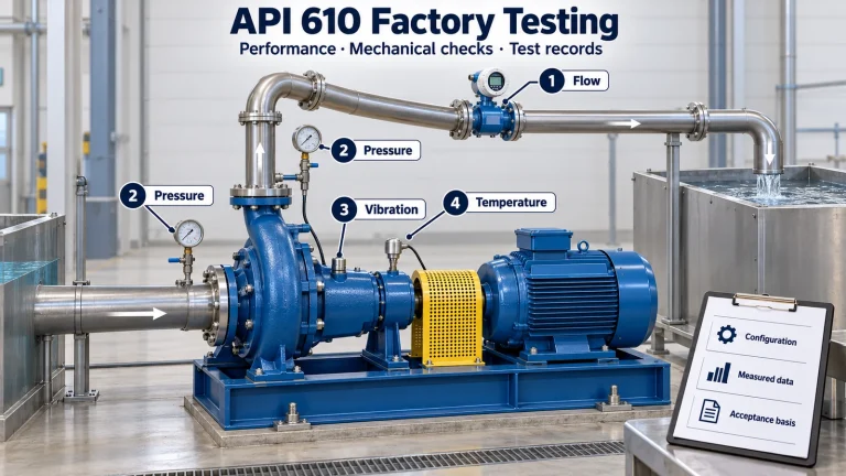
Use accessible, repeatable points on the pump and motor bearing housings. Record horizontal, vertical, and axial directions (H/V/A) wherever the design and access allow. Keep the location, sensor type, and mounting method consistent when comparing trends.
| Data group | What to record |
|---|---|
| Equipment | model, size, rated and actual speed, motor, bearings, and coupling configuration. |
| Measurement | location and direction, instrument/sensor, mounting, units, overall RMS value, and, when needed, FFT, waveform, phase, or high-frequency measurement. |
| Operating conditions | flow, suction and discharge pressure, liquid level, temperature, fluid, valve position, VFD speed, and status of parallel pumps. |
| Context | operating hours, process changes, alarms, lubrication/alignment history, and photos of the nameplate and measurement locations. |
03 · Read signal patterns
Pump vibration causes: how to read the signals
Frequencies help guide an investigation, but no single frequency confirms a failure. The response depends on the pump, support structure, speed, load, sensor, and combination of conditions. Use the following as a list of hypotheses and confirm each one with measurements and physical checks.
A peak near 1× running speed
Imbalance is one possibility, but eccentricity, a bent shaft, resonance, hydraulic forces, and other synchronous excitation can also produce a 1× response. Record actual speed, phase, H/V/A, waveform, and how the signal changes with load or speed. Check the impeller, coupling, runout, and structure before deciding that balancing is required.
A 2× component, harmonics, or elevated axial/radial response
Misalignment can produce 1× or 2× components, but it is not the only cause. Looseness, soft foot, rubbing, a bent shaft, and base flexibility can also create harmonics or change phase. Compare both sides of the coupling, measure axially and radially, and follow the alignment procedures for the manufacturer and coupling. Do not use one fixed phase value as proof.
Blade-pass frequency (BPF)
As a candidate frequency, BPF = number of impeller vanes × RPM / 60 when expressed in Hz. A response near BPF or its harmonics may relate to interaction between the impeller and volute or guide vanes, clearances, or nonuniform flow. Confirm vane count and speed, then compare the spectrum with flow, the pump curve, and pressure changes. BPF alone does not prove recirculation or impeller damage.
Bearing impacts or characteristic frequencies
BPFO, BPFI, BSF, and FTF depend on bearing geometry and speed. Use the correct bearing model and manufacturer or analyzer data; do not compare a calculated frequency for a different bearing. A trend in high-frequency or envelope energy can help detect early impacts, but also review lubrication, contamination, fit, temperature, and other equipment data.
Broadband energy or vibration that changes with the process
Cavitation, entrained air, suction restrictions, turbulence, low-flow recirculation, and bearing damage can produce broadband signals or noise. Review flow, suction pressure, liquid level, temperature, strainer/filter condition, and the pump curve together. Gravel-like noise or energy in one frequency band is not enough to diagnose cavitation.
A change after connecting piping or modifying the installation
A change in alignment or vibration after a modification may indicate piping loads, changed supports, disturbed flow, or base distortion. Compare alignment and position records under the conditions required by the installation procedure. Do not loosen flanges on a live line to perform a test; any disconnection requires isolation, depressurization, a work permit, and the applicable engineering procedure.
04 · Separate system and machine clues
How to distinguish hydraulic from mechanical causes
A signal that changes with flow, liquid level, suction pressure, temperature, or valve position directs the investigation toward the hydraulic system and operating point. A signal that follows speed, has repeatable phase, or coincides with looseness, temperature, or bearing condition may point toward a mechanical cause. Both can coexist: a suction problem can damage an impeller, and piping loads can change alignment.
Compare the actual operating point with the approved pump curve and operating range. For NPSHa, NPSHr, and operation outside the intended range, see our guide to NPSH, POR/AOR, and BEP. For piping loads and nozzle forces, see the guide to pump nozzle forces and moments.
05 · Follow the field workflow
A practical field troubleshooting sequence
- Confirm safety and measurement quality. Follow site alarms and permits; record instrument, sensor, mounting, units, speed, and measurement location.
- Repeat the reading. Use the same H/V/A points and compare with the equipment baseline.
- Fix the operating conditions in the record. Note flow, pressures, level, temperature, fluid, valves, VFD, and parallel pumps.
- Review the curve and trend. Locate the actual point on the approved curve and compare measurements at pump and motor bearings without averaging different locations.
- Check external causes. Review base, grout, anchors, soft foot, coupling, alignment, supports, suction conditions, and recent piping changes.
- Use FFT, waveform, and phase to discriminate between hypotheses. Consider running speed, BPF, and bearing frequencies calculated for the installed model; document the method used.
- Inspect and remeasure when the evidence supports it. Plan disassembly under the applicable isolation procedure. Correct a documented cause and repeat measurements under comparable conditions.
06 · Apply the right acceptance basis
Vibration limits: measurement, acceptance, and alarms
Overall RMS is useful for comparing measurements when location, direction, speed, and method remain consistent. A factory or field acceptance criterion and a plant operating alarm answer different questions; neither identifies the root cause by itself.
ANSI/HI 9.6.4-2022 addresses vibration measurement on stationary parts associated with bearings, including bearing housings, and gives allowable values under defined test conditions. The applicable criterion depends on the pump, speed, test environment, and measurement basis; consult the relevant edition, its 2024 erratum, the manufacturer, and the project specification. For limits and acceptance criteria, see our guide to ANSI/HI 9.6.4-2022.
Do not use one alarm value for every machine
Applicable limits depend on the pump, speed, test condition, measurement location, manufacturer guidance, and project requirements.
07 · Verify repair or replacement
When to inspect the power end, impeller, or complete pump
Consider an internal inspection when measurements, history, and external checks indicate possible damage to the shaft, bearing, housing, impeller, or casing. Before ordering a part, identify the model, size, configuration, speed, materials, interfaces, and operating point.
- Shaft, bearing, or housing damage: evaluate repair or power-end replacement after confirming shaft, fits, interfaces, and housing condition.
- Impeller damage or hydraulic wear: confirm type, diameter, material, clearances, curve, and cause of damage before selecting a replacement.
- Casing damage or changed service: consider a complete pump if repair cannot restore the required integrity, materials, or capacity.
- Piping, support, control, or operating-point issue: correct the system first; replacing the pump may reproduce the same pattern.
For a Goulds installation, see our Goulds 3196 replacement information; for a Durco installation, review Durco Mark III replacement options. Brand references help identify a configuration, but do not establish that every size, assembly, or curve is interchangeable. Verify drawings, dimensions, fits, materials, and service conditions before requesting a quotation.
Request an engineering review
Share the model and size, speed, flow and pressures, H/V/A points, readings and units, FFT or waveform if available, temperature, recent changes, maintenance history, and photos of the nameplate and equipment. We can review what information is missing to determine whether inspection, repair, or a verified replacement should be evaluated.
Frequently asked questions
Frequently asked questions
What should I check first when an ANSI pump vibrates?
Confirm that the reading is repeatable and that the instrument, units, speed, mounting, and location are correct. Then record flow, pressure, temperature, suction conditions, and recent changes before attributing the problem to a bearing.
Does a 1× frequency prove imbalance?
No. It may indicate imbalance, eccentricity, resonance, or another synchronous force. Compare phase, direction, trend, speed, and physical condition before drawing a conclusion.
Can piping loads cause pump vibration?
Yes. Piping loads can distort the casing, change alignment, or transfer loads to the base. Evaluate the installation using a safe procedure and the manufacturer and project criteria.
Is there a universal vibration limit?
No. Applicable values depend on pump type, speed, support, measurement, and test condition. Consult ANSI/HI 9.6.4, the manufacturer, and project requirements; plant alarm settings require their own criteria.
Sources and related reading
Technical references
- ANSI/HI 9.6.4-2022 — Rotodynamic Pumps for Vibration Measurements and Allowable Values (measurement scope and allowable values).
- Hydraulic Institute — 2024 erratum to ANSI/HI 9.6.4-2022.
- Hydraulic Institute — rotodynamic pump standards, including guidance on NPSH, operating regions, monitoring, and piping.
- Guide to ANSI/HI 9.6.4-2022 vibration measurements and allowable values.
- ANSI Pumps Pro technical resources and OEM part number cross-reference.