A low-flow, high-head duty can be suitable for an OH2 pump when its hydraulic design, operating limits and mechanical configuration match the process. The review should establish how the selected impeller and casing produce the required head, how minimum flow is maintained, and what manufacturing and test evidence supports the selection.
OH2 identifies a pump arrangement. It does not establish the hydraulic performance of a particular size. Begin with the duty range and liquid properties, then compare the actual curve, protection requirements and supplied configuration.
What Makes a Duty Low-Flow and High-Head?
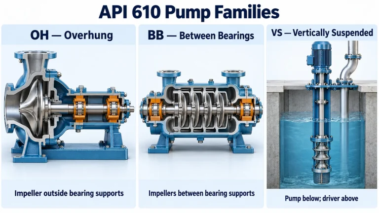
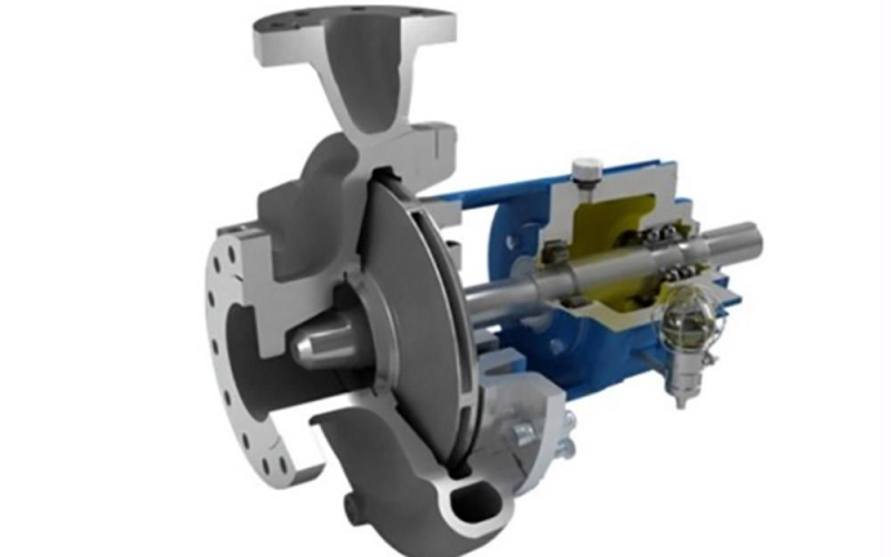
OH2 describes a single-stage, overhung, centerline-mounted pump configuration. “Low flow” and “high head” describe its duty. A project may require that configuration and still need a dedicated hydraulic selection.
Distinguish a pump designed for a small capacity from a larger pump operated far below its own best efficiency point, or BEP. The same process flow can be appropriate for one hydraulic size and unsuitable for another.
There is no universal flow rate that separates acceptable and unacceptable OH2 service. Record minimum, normal, rated and maximum flow; total head; suction conditions; operating temperature; density; viscosity; vapor pressure; and solids. Include the purchasing specification and expected duration of each operating case.
For a project requiring OH2 construction, start with an API 610 OH2 selection review. For an ANSI replacement application, use the separate LF3196 and Mark 3 Lo-Flo selection guide.
Calculate Specific Speed on a Consistent Basis
Specific speed helps compare hydraulics when the calculation uses consistent units and a defined BEP. For this guide, use:
n = rotational speed, rpm.
QBEP = BEP flow, m³/s; HBEP,stage = head per stage at BEP, m.
Use a consistent convention. Check total-flow versus flow-per-eye definitions for double-suction impellers.
Ns,US uses rpm, US gpm and ft; nq above uses rpm, m³/s and m.
The relationship assumes the same BEP, stage and flow basis. A convention using 3.65 × nq gives a different numerical value.
Some references use different symbols or numerical conventions. Check the calculation basis before comparing reported values. Hydraulic Institute pump principles gives the unit conventions and flow definitions.
As an illustrative example, assume a selected hydraulic design has its BEP at 10 m³/h and 200 m head per stage at 2,950 rpm. Converting flow to 0.002778 m³/s gives n_q of approximately 2.92. This is an assumed BEP, not a tested product selection. A requested process duty alone does not establish the selected pump’s BEP.
Illustrative assumed BEP: 10 m³/h, 200 m per stage, 2,950 rpm.
US specific speed is approximately 151 on the same flow basis. This example is not a manufacturer curve or product guarantee.
Compare Low-Flow OH2 Hydraulic Designs
The impeller, collector and discharge arrangement work together. Reviewing an impeller in isolation can miss the reason a low-flow design performs as intended.
Low-specific-speed closed impellers may have narrow passages that complicate casting, cleaning and inspection. Dedicated radial-vane or Barske-style hydraulics offer another approach. Circular casing and diffuser arrangements also deserve consideration.
Public manufacturer examples demonstrate this variety. KSB RPH-LF uses a circular casing; Sulzer OHHL uses a dedicated low-flow impeller-diffuser design; and Flowserve HPXM describes radial blades with a customized casing or insert. These examples establish available design approaches, not interchangeable performance.
| Hydraulic approach | Review focus | Evidence to request |
|---|---|---|
| Conventional OH2 hydraulics | Whether the actual process range suits the selected curve | Pump-specific operating limits and performance data |
| Dedicated radial-vane or Barske-style impeller | Matching the impeller to the collector, clearances and liquid | Selected configuration, curve and minimum-flow basis |
| Circular casing and diffuser arrangement | Off-design loading, curve shape and discharge geometry | Hydraulic and mechanical verification for the supplied design |
| Closed impeller with narrow passages | Reproducible geometry, cleaning and inspection access | Passage inspection, drawing compliance and relevant testing |
Avoid assuming that a circular casing eliminates all radial load or that every Barske-style design has the same allowable flow range. Ask for evidence for the proposed size, speed and liquid.
Request an OH2 duty-point review with the flow, head, liquid and temperature you already know. An existing curve or specification helps define the next review.
Check Minimum Flow, NPSH and Curve Stability
A pump’s head at the requested flow is only one part of its operating assessment. Check the preferred and allowable operating regions and the supplier’s minimum-flow restrictions. The Hydraulic Institute operating-region overview explains why operation away from BEP can affect loading, vibration and reliability.
Minimum continuous stable flow, MCSF, concerns stable operation. Minimum continuous thermal flow, MCTF, addresses thermal restrictions. A suitable operating arrangement must respect both, together with any more restrictive suction, seal or process requirement. Their values must come from the selection and service review.
If the process demand is below the required pump through-flow, assess a minimum-flow return system. Record where it returns, how it is controlled and how it affects system temperature and suction conditions. A return directly to suction needs a heat and system assessment; circulating liquid does not necessarily remove heat from the overall loop.
Mechanical-seal circulation is a separate function. For example, API Plan 13 returns liquid from the seal chamber to suction and requires an appropriate pressure difference. It is not automatically a substitute for the pump’s minimum-flow protection.
Compare system NPSH available with the pump requirement and the applicable margin across relevant conditions. Use the NPSH available calculation guide to organize the system inputs. An inducer may be an option for a selected design, but its benefit and operating range need verification.
Use a heat balance as a screening tool
Liquid heating depends on the losses transferred to the liquid and the available through-flow. A bulk heat balance helps organize the inputs, while the manufacturer establishes the thermal operating restriction for the actual liquid and pump.
ΔT = bulk temperature rise, K; Pheat = heat transferred to liquid within the defined boundary, W.
ρ = kg/m³; Q = through-flow, m³/s; cp = specific heat capacity, J/(kg·K).
This is a simplified steady-flow heat balance, not a stand-alone MCTF method. It excludes zero-flow transients and local recirculation; Pheat is not automatically the entire shaft power.
Review Speed, Power and Pressure Together
A speed change alters hydraulic and mechanical conditions. For the same impeller under the assumptions of the affinity relationships, flow scales with speed, head with speed squared and power with speed cubed. Those estimates do not prove that changing the motor preserves the original duty. A redesigned selection at the same flow and head also cannot be assigned the power increase of an unchanged impeller. See the Hydraulic Institute pump-curve reference.
Q = flow; H = head; P = absorbed shaft power; n = speed.
Use consistent units for each ratio. These are estimates for the same impeller under similarity assumptions, not approval to replace a driver.
At a defined duty:
Pshaft = pump shaft power, kW; ρ = liquid density, kg/m³.
g = 9.81 m/s²; Q = flow, m³/s; H = total head, m.
ηpump = pump efficiency as a decimal. Motor and drive efficiency are separate.
At 10 m³/h and 200 m, with density of 1,000 kg/m³, hydraulic power is 5.45 kW. Assuming 30% pump efficiency gives approximately 18.17 kW shaft power; assuming 45% gives approximately 12.11 kW. These efficiencies illustrate the calculation and do not represent a product guarantee. Driver selection still requires the absorbed-power curve and project operating cases.
Disc friction is one loss to review in low-specific-speed designs. Its diameter and speed dependence is strong, while the coefficient depends on the fluid, surface condition and side-gap geometry. KSB’s disc-friction reference explains these dependencies. A simplified scaling relationship should not become an exact efficiency prediction for a finished pump.
Pdf = disc-friction power loss; ω = angular speed, rad/s; D2 = impeller outside diameter, m.
The coefficient depends on Reynolds number, roughness and side-gap geometry. Holding the relevant coefficient and similarity assumptions constant is essential when applying this trend.
Δp = equivalent differential pressure, bar; ρ = kg/m³; H = m.
At ρ = 1,000 kg/m³ and H = 200 m, the equivalent differential pressure is 19.62 bar. Suction pressure, shutoff and temperature must be reviewed separately.
Head also needs a pressure interpretation. At the example density, 200 m corresponds to approximately 19.62 bar differential pressure. Add the suction pressure and examine shutoff, temperature and transient conditions when reviewing the pressure boundary. Differential head does not establish casing or seal-chamber pressure capability.
Manufacture the Impeller Without Losing Its Hydraulic Geometry
The manufacturing route must reproduce the approved geometry and provide access for the required inspections. A narrow closed passage may be difficult to form, clean and inspect; a more accessible design may introduce different clearance or surface requirements.
| Route | Potential use | Controls to establish |
|---|---|---|
| Cast impeller with conventional tooling | Qualified geometry and repeatable production | Core location, filling, solidification, cleaning and inspection |
| 3D-printed mould or core | Complex or revised casting geometry | Printed-core quality, process qualification and finished dimensions |
| Machining from suitable stock or forging | Geometry with adequate tool access | Material condition, reach, wall thickness and inspection |
| Controlled internal finishing | Removing residue and achieving specified surface condition | Material removal, passage dimensions, edges and final cleanliness |
3D sand printing has been investigated for pump impeller manufacture, including a 2022 published study. It is a route to evaluate, not evidence that a supplier’s proposed casting meets the project requirements.
Do not prescribe a universal internal Ra value without specifying the location, measurement method and drawing requirement. Abrasive-flow finishing also needs qualification: it must achieve the intended result without changing the accepted geometry.
Five-axis machining cannot be assumed to reach every fully enclosed passage. Equally, machining from forging does not remove the need for material verification or inspection. Select the route against the actual part.
The custom casting and machining review and manufacturing inspection process provide routes for discussing the required component and documentation scope.
Ask for Mechanical and Quality Evidence
An OH2 designation does not prove compliance with every project requirement. Identify the specified API edition, purchaser supplements, options and deviations before approving the equipment.
| Review area | Useful supplier deliverable |
|---|---|
| Performance | Curves for the selected size, speed, impeller and stated liquid basis |
| Operating limits | MCSF, MCTF, allowable range and protection requirements |
| Rotor and bearings | Applicable loading, deflection and bearing-life calculations with assumptions |
| Seal system | Seal-chamber pressure and temperature, arrangement and auxiliary requirements |
| Geometry | Approved drawing, critical dimensions and passage inspection records |
| Materials | Specified grades, traceability and required material/NDE records |
| Balance and assembly | Applicable balance requirement, residual unbalance and assembly clearances |
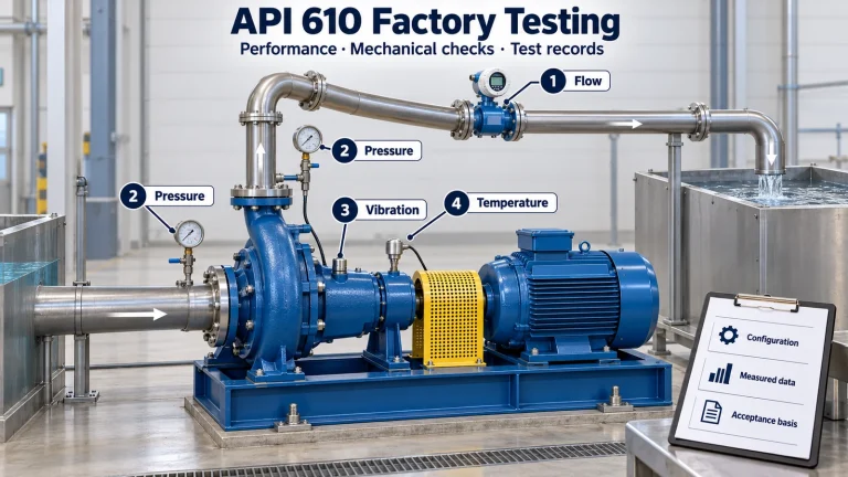
| Testing | Agreed performance, pressure and vibration records with acceptance criteria |
For balancing references, identify the applicable standard and project requirement. ISO 21940-11 covers balancing procedures and tolerances for rigid rotors and succeeds the withdrawn ISO 1940-1. A balance-grade label alone is not a complete acceptance record.
Specified bearing life is a calculation under defined assumptions. It should not be presented as a guaranteed maintenance-free interval. Similarly, a mechanical limit needs its measurement location, operating cases and governing specification.
When Should You Compare OH2 with Other Pump Types?
Compare alternatives when the proposed OH2 cannot demonstrate a suitable duty range, suction condition, pressure boundary or economical protection arrangement.
Sundyne’s OH6 approach uses an integral speed-increasing gearbox for low-flow, high-head service. Its evaluation should include the complete drive and auxiliary package.
Two-stage or multistage designs can distribute head across stages, but their suitability still depends on the actual hydraulic and mechanical selection. Keep classifications precise: BB2 commonly covers single- and two-stage radially split between-bearings designs; other multistage arrangements have their own classifications. Sulzer’s product overview gives examples.
Very small flow, metering requirements or particular liquid properties may also justify considering a positive-displacement alternative with the appropriate protection and project requirements.
Compare complete proposals at the same duty and operating range: equipment, recycle losses, auxiliaries, maintenance access, spare parts and supporting records. Published maximum capacities and heads are not a substitute for that comparison.
- Define dutyFlow range, head and liquid
- Check hydraulicsCurve and selected configuration
- Check protectionMinimum flow, NPSH and heat
- Compare alternativesMechanical scope and total cost
- Verify evidenceDrawings, materials and tests
- Confirm selectionProject requirements and deviations
Compare arrangements and test evidence
Use the construction guide when comparing OH2 with geared or between-bearings alternatives, then carry the selected configuration into the factory-test requirements.
What to Send for an Engineering Review
Begin with flow, head, liquid and temperature. Add suction pressure or NPSH available, viscosity, solids, operating range and electrical frequency where known. An existing datasheet, performance curve or purchasing specification is useful.
For a replacement, include the installed model, nameplate, impeller information and available drawings. Hydraulic suitability, dimensions, materials and interfaces require separate checks. The API 610 and ASME B73.1 selection guide explains the standards context.
Request an OH2 Duty-Point Review
Send the information you already have. The review can identify the additional curve, manufacturing and project evidence required for the proposed selection.
Frequently Asked Questions
Can an OH2 pump handle low-flow, high-head service?
Yes, a suitable OH2 design can handle this duty. Confirm the actual hydraulic selection, operating limits, suction conditions, mechanical requirements and supporting test or calculation records for the proposed configuration.
Is there a universal low-flow limit for OH2 pumps?
No. A flow value or percentage of BEP is not a universal safe limit. Use the selected pump’s operating range, minimum stable and thermal flows, liquid properties and project requirements.
Are Barske impellers mandatory for low-flow OH2 duties?
No. Barske-style and other radial-vane designs are options. Select the impeller, casing and diffuser arrangement from the required duty and verified performance rather than treating one design as mandatory for every application.
What is the difference between MCSF and MCTF?
MCSF concerns stable continuous operation; MCTF concerns thermal restrictions. The operating arrangement must respect both, together with any more restrictive suction, seal, manufacturer or process requirement.
Can a higher-speed motor solve the problem?
It may be part of a new selection, but a motor change alone does not establish suitability. Review the curve, absorbed power, NPSH, pressure boundary, shaft, bearings, seal and driver at the proposed speed.
What data should a supplier provide before selection?
Request the selected pump curve, operating limits, liquid and speed basis, minimum-flow requirements, material and inspection scope, mechanical verification and applicable project-standard compliance or deviations.
Technical references
- Hydraulic Institute — Pump Principles
- Hydraulic Institute — Pump Curves
- Hydraulic Institute — NPSH and Operating Regions
- KSB — Disc Friction
- KSB RPH-LF — Circular-Casing OH2 Example
- Sulzer OHHL — Low-Flow Impeller and Diffuser Example
- Flowserve HPX / HPXM — Radial-Vane Hydraulic Example
- ISO 21940-11 — Rigid-Rotor Balancing
- Hernández and Fragoso (2022) — 3D Sand Printing and Impeller Casting
Manufacturer examples describe their own designs. They do not establish this supplier’s product performance. Standard compliance must be reviewed against the purchaser-specified edition and requirements.