

Technical Review Basis: This guide was reviewed using available pump drawings, ASME B73.1 dimensional principles, hydraulic curves, material specifications and internal inspection procedures. Final compatibility must be confirmed for the specific pump and installation.
What Does Goulds 3196 Compatible Mean?
The word compatible can describe several different levels of suitability.
Installation compatibility: The replacement pump fits the existing piping, baseplate, motor, coupling, shaft centerline and maintenance envelope.
Assembly compatibility: The replacement wet end or component fits the retained bearing frame, shaft, sleeve, seal chamber, rear cover, gaskets and impeller connection.
Hydraulic compatibility: The replacement can meet the required flow, head, speed, efficiency, motor power, NPSH margin and operating range.
Material compatibility: The supplied alloy, elastomers and seal materials are suitable for the process fluid and operating temperature.
A supplier should state which level of compatibility has been evaluated. Fits a Goulds 3196 is not precise enough for engineering approval.

Step 1: Identify the Exact Pump Configuration
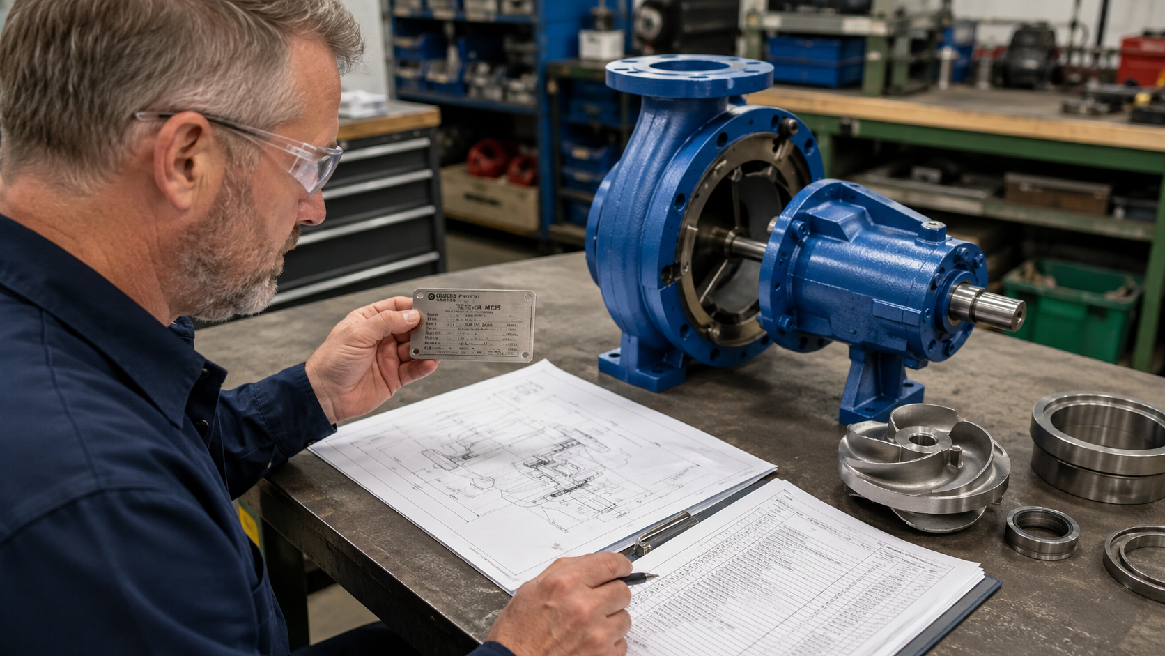
Begin with complete equipment identification. Record: manufacturer, full pump model, pump size, frame designation, serial number, impeller diameter, operating speed, rotation direction, casing material, impeller material, seal chamber type, shaft or sleeve arrangement, mechanical seal model, coupling type, motor frame and original part number.
Goulds 3196 installations may use different frame and component configurations. The family name alone does not identify the required replacement.
Information to send the supplier: Provide nameplate photograph, overall installation photographs, sectional drawing, outline drawing, pump datasheet, current pump curve, existing component photographs, measured critical dimensions and previous repair or modification history. When documents are unavailable, the supplier should identify which site measurements are required before manufacturing.
Step 2: Verify External Installation Dimensions
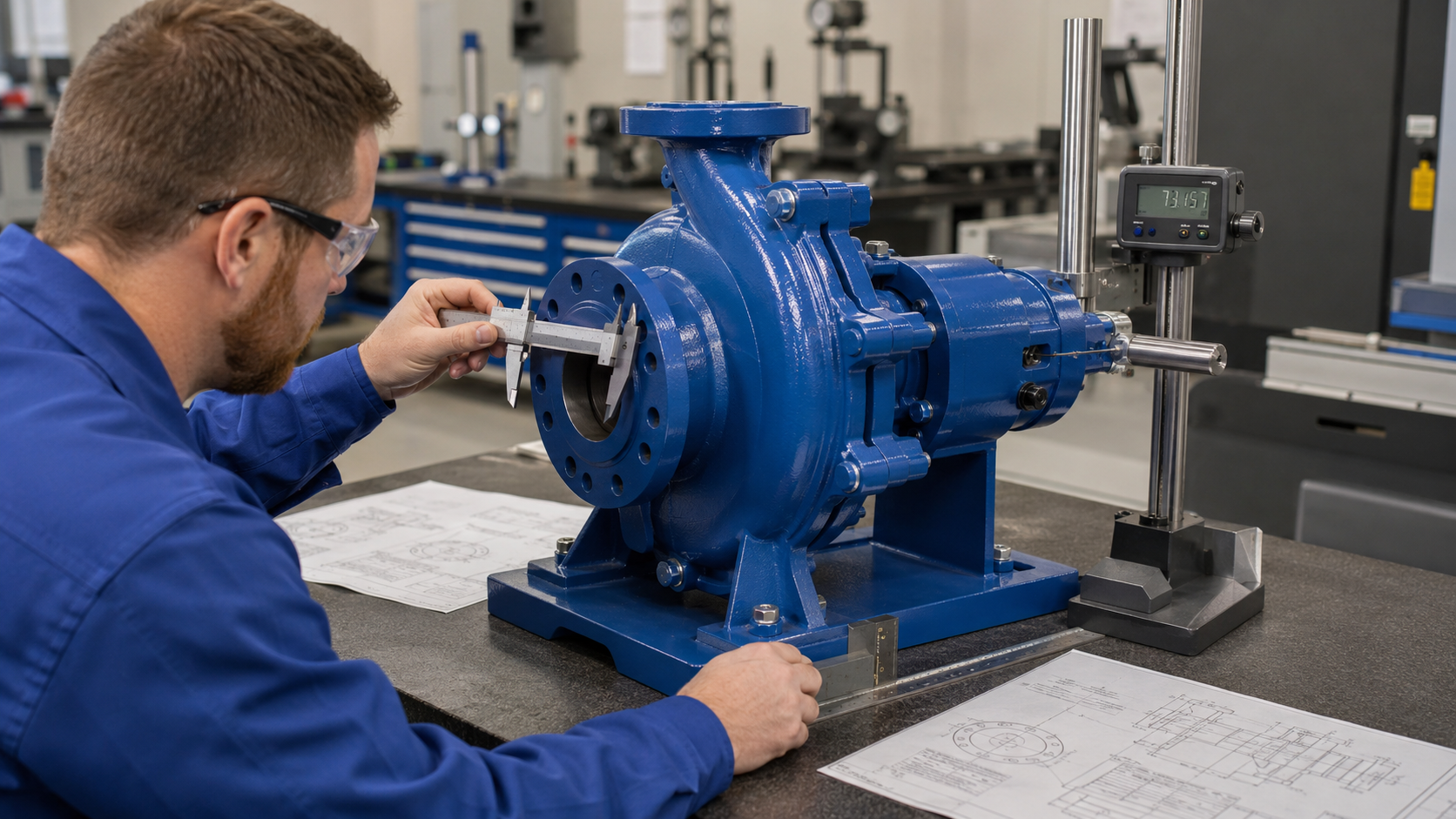
For a complete replacement pump, compare the proposed unit with the existing installation.
Flange interfaces
Verify: suction flange size, discharge flange size, pressure class, flange facing, bolt-hole number, bolt-circle diameter, flange orientation, suction nozzle coordinates and discharge nozzle coordinates. Matching nominal flange size does not prove that the piping interfaces will align.
Shaft centerline and pump feet
Verify: shaft centerline above mounting surface, pump foot dimensions, foot bolt-hole spacing, hole diameter, baseplate mounting surface, expected shim requirement and motor shaft height.
Coupling position
Verify: shaft extension diameter, shaft extension length, keyway, coupling hub bore, distance between shaft ends, spacer length and coupling guard clearance. A replacement pump may match the piping but still require changes to the motor or coupling.
Site condition: The final installation review should also consider baseplate flatness, foundation condition, soft foot, piping strain, previous field modifications, thermal movement and maintenance removal space. A dimensional drawing cannot prove that the existing site remains in its original condition.
Step 3: Verify Internal Mechanical Interfaces
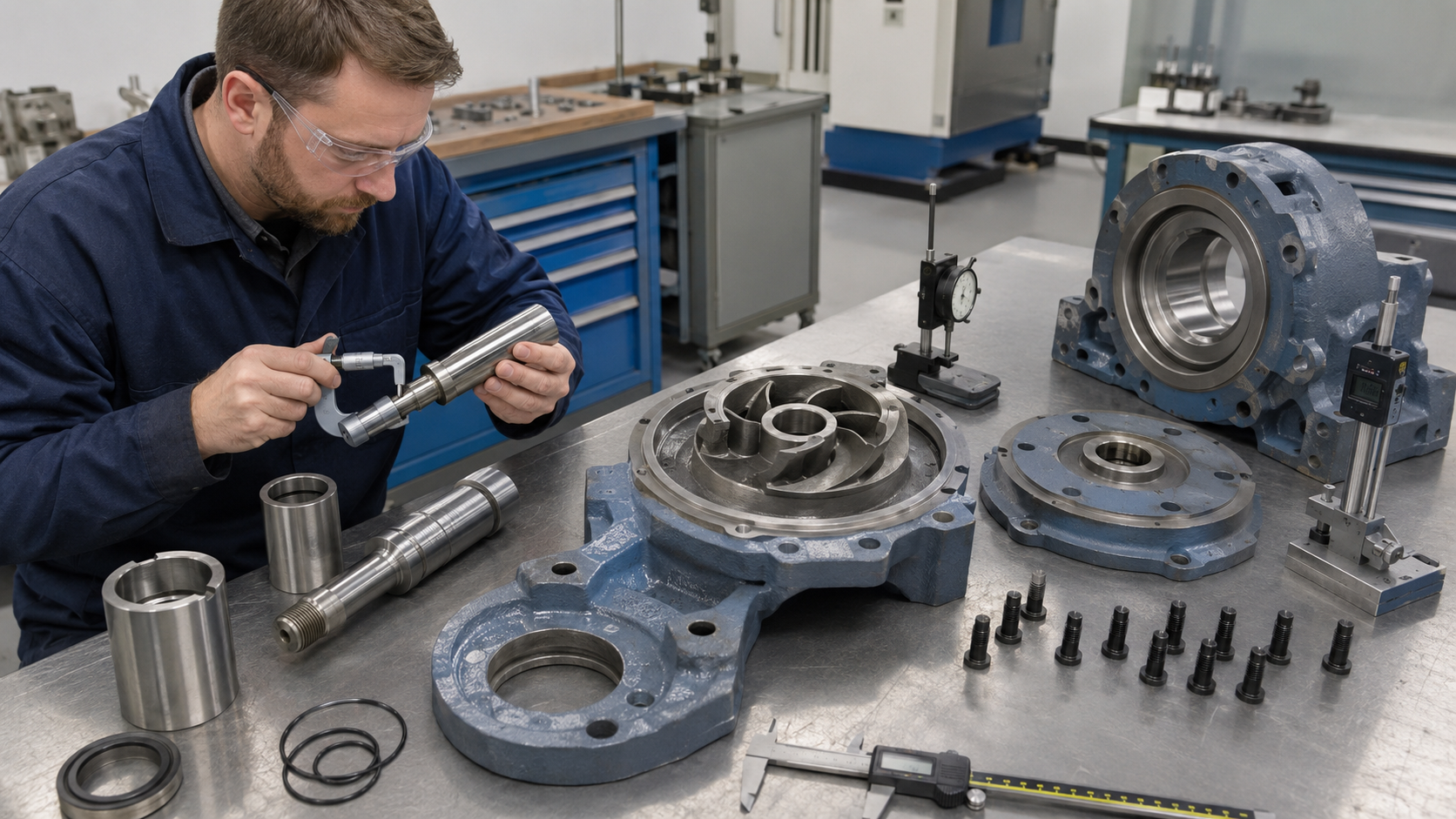
When replacing a wet end or individual component, internal interfaces are more important than external footprint.
Casing-to-frame interface
Confirm: frame register, rear-cover fit, gasket location, bolt pattern, axial position and concentricity.
Impeller interface
Confirm: impeller type, rotation, bore or thread, keyway, hub length, axial position, running clearance, vane geometry, outside diameter, inlet-eye diameter and balance condition. An impeller can attach to the shaft and still be hydraulically unsuitable.
Shaft and sleeve
Confirm: shaft diameter, sleeve inside diameter, sleeve outside diameter, sleeve length, shoulder position, O-ring location, surface finish, runout and thread or locking arrangement.
Seal chamber
Confirm: chamber type, chamber bore, chamber depth, gland pilot, gland bolt pattern, shaft or sleeve diameter, flush-port size, flush-port orientation and mechanical seal envelope. Do not assume that the existing seal can be reused until the complete seal interface has been reviewed.
Tolerance stack: Individual components may each pass inspection but still create an assembly problem when their tolerances combine. For a wet-end kit or rotating assembly, request verification of the complete assembled interface, not only isolated component dimensions.
Step 4: Review Hydraulic Performance
Dimensional compatibility does not guarantee hydraulic suitability.
Required operating data: Provide flow, differential head, operating speed, fluid density, viscosity, temperature, vapor pressure, solids content, suction pressure, discharge pressure, NPSH available, motor rating and expected operating range.
Pump curve review: Compare rated flow and head, impeller diameter, efficiency, absorbed power, NPSHr, shutoff head, minimum continuous stable flow and preferred operating region. The replacement curve does not need to be mathematically identical to the original curve. It must be suitable for the required operating point and system conditions.
NPSH: Nozzle size and position do not determine NPSH compatibility. NPSHr depends on impeller inlet geometry, speed, flow, pump design and operating point. Review the replacement pump NPSHr against the available system margin.
Motor power: Confirm that the replacement will not overload the installed motor at the design point or elsewhere in the expected operating range.

Step 5: Confirm Materials and Inspection Documents
The quotation should identify the exact casting or wrought material grade. Generic descriptions such as stainless steel, duplex or Hastelloy are not sufficient for final approval.
Material selection should consider: fluid composition, concentration, temperature, chloride content, oxidizing or reducing conditions, solids, velocity, aeration, cleaning chemicals and expected corrosion mechanism.
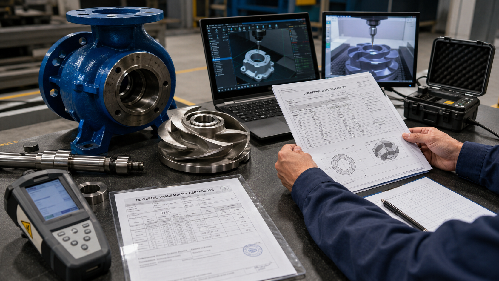
Material documentation: Depending on the order, request material test report, heat number, casting identification, chemical composition, mechanical properties, heat-treatment record, PMI report, nondestructive examination report, repair-welding record and third-party inspection report. The component heat number should match the supplied material documentation.
Dimensional inspection: The dimensional report should show component identification, drawing number, nominal value, measured value, feature-specific tolerance, inspection tool, inspection date, result and inspector. Avoid reports that only state 100% compatible without measured values.
Component-specific testing: Different components require different inspection plans. A casing may need hydrostatic testing. An impeller may need dimensional and balance records. A shaft may need runout and material records. A complete pump may need performance testing. The purchase order should define which documents and tests are required.
Supplier Warning Signs
Be cautious when a supplier: guarantees compatibility without asking for the full pump model; does not request the pump size or frame; uses one tolerance for every dimension; promises zero field modification without reviewing the installation; cannot provide a dimensional drawing; only supplies generic material descriptions; guarantees identical performance without a curve; cannot link the MTR to the component heat number; cannot distinguish a wet-end kit from a rotating assembly; provides the same quality certificate for unrelated components; uses only the product-family name for cross-reference.
A qualified supplier should be able to explain exactly what was reviewed and what remains the installer responsibility.
Incoming Inspection Checklist
Before releasing the replacement for assembly, verify:
- Pump configuration: Nameplate, model, size and frame
- Component identity: Part number or approved cross-reference
- Critical dimensions: Measured dimensional report
- Impeller: Diameter, rotation, runout and balance
- Shaft and sleeve: Dimensions, finish and runout
- Seal chamber: Bore, depth, gland and port interfaces
- Material: MTR and heat-number traceability
- Pressure boundary: Hydrostatic certificate when required
- Hydraulic duty: Approved curve or test data
- Final release: Inspection approval and photographs
Frequently Asked Questions
Is every Goulds 3196 replacement part interchangeable?
No. Compatibility depends on the pump size, frame, part, material, impeller arrangement and design revision.
Can I replace only the wet end?
Possibly. The casing register, rear cover, impeller connection, shaft or sleeve, seal chamber and gasket interfaces must be verified.
What is normally included in a wet-end kit?
A wet-end kit may include the casing, impeller, rear cover or seal chamber, sleeve, gaskets and related hardware. Exact scope varies by supplier. Bearings and bearing frames are generally part of the power end.
Can the existing mechanical seal be reused?
Only when the shaft or sleeve diameter, seal chamber bore and depth, gland pilot, bolt pattern and seal operating length are compatible.
Does ASME B73.1 guarantee Goulds 3196 interchangeability?
No. ASME B73.1 standardizes important dimensional and design features, but exact pump and component compatibility must still be verified.
Can matching dimensions guarantee equal pump performance?
No. Hydraulic performance must be reviewed using the proposed curve, impeller diameter, speed and process conditions.
Request a Goulds 3196 Compatibility Review
Send us: pump nameplate photograph, full pump model, size and frame, part number, impeller diameter, required material, seal information, process fluid and temperature, flow and head, and installation photographs or drawings.
ANSI Pumps Pro can review the available information and identify which dimensional, hydraulic, mechanical and material checks are required before quotation.