The Most Overlooked Cause of Pump Failure
Ask any experienced pump reliability engineer what causes premature failures, and they’ll tell you: poor intake design. Studies by the Hydraulic Institute show that over 70% of pump vibration, cavitation, and bearing failure problems originate from improper suction conditions — and most of these could have been prevented by following the guidelines in ANSI/HI 9.8.
ANSI/HI 9.8 — “Pump Intake Design” — provides the engineering standard for designing pump suction piping, sumps, tanks, and intake structures that deliver uniform, swirl-free flow to the pump impeller. This guide explains the key principles and how they directly impact the pumps you maintain and rebuild.
The Physics of Bad Intake Flow
When a pump impeller receives uneven, swirling, or air-entrained flow, three things happen:
⚠️ Quality & Compliance Assurance
All pumps and components from ANSI Pumps Pro are manufactured to ASME B73.1 dimensional specifications. Every shipment includes certified Material Test Reports (MTRs), CMM dimensional inspection reports, and hydrostatic test certificates (1.5× MAWP). We guarantee 100% dimensional interchangeability with Goulds 3196 and Durco Mark III. Full material traceability from heat number to your receiving dock.
- Hydraulic imbalance: The impeller experiences asymmetric loading, generating vibration at 1× RPM and vane-pass frequency.
- Localized cavitation: Uneven velocity distribution creates low-pressure zones even when the bulk NPSH margin appears adequate.
- Pre-rotation: Swirling flow entering the impeller eye changes the velocity triangle, reducing head, efficiency, and causing unpredictable performance.
These problems often get blamed on “bad pumps” when the real culprit is in the approach piping or sump design.
Key Intake Design Rules from ANSI/HI 9.8
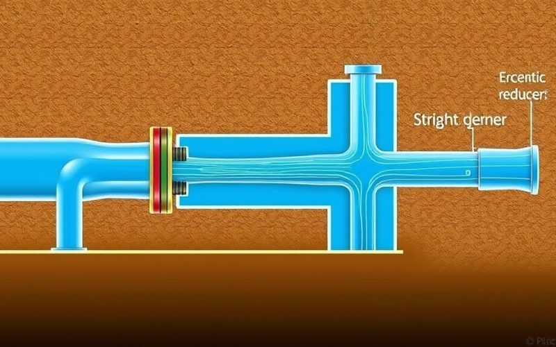
1. Straight Pipe Before the Suction Flange
The single most important rule: provide 5 to 10 pipe diameters of straight run immediately upstream of the pump suction flange.
| Fitting upstream of pump | Minimum straight run required |
|---|---|
| Concentric reducer (horizontal pump) | 5× pipe diameter |
| Eccentric reducer (flat side up) | 5× pipe diameter |
| 90° elbow (in-plane with impeller) | 7× pipe diameter |
| 90° elbow (out-of-plane) | 10× pipe diameter |
| Tee or branching connection | 10× pipe diameter |
| Control valve | 7× pipe diameter |
2. Submergence: Preventing Vortex Formation
When pumping from an open tank or sump, insufficient liquid submergence above the suction inlet causes free-surface vortices that pull air directly into the impeller.
| Flow rate (GPM) | Bell diameter (in) | Minimum submergence (in) | Minimum floor clearance (in) |
|---|---|---|---|
| 500 | 8 | 16 | 4 |
| 1000 | 12 | 24 | 6 |
| 2000 | 16 | 32 | 8 |
| 4000 | 20 | 40 | 10 |
Common Intake Problems Found in the Field
“My rebuilt pump vibrates, but it balanced perfectly in the shop”
If a pump runs smoothly on your test stand but vibrates after field installation, the problem is almost certainly in the piping. Check:
- Is there a concentric reducer mounted directly to the suction flange? (Should be eccentric, flat side up)
- Is there an elbow within 5 diameters of the suction flange?
- Is the suction pipe properly supported, or is it hanging from the pump nozzle?
Retrofit Solutions for Existing Installations
If you’re maintaining pumps with chronic intake-related problems, several retrofit options exist without replacing the entire sump or piping:
- Flow straighteners: Install a stainless steel honeycomb or tube bundle flow straightener in the suction pipe, at least 3 diameters upstream of the pump.
- Vortex breakers: For open sumps, add a cross-shaped breaker plate just below the surface above the suction bell.
- Suction stabilizers: A pulsation dampener on the suction line can absorb hydraulic noise and reduce cavitation damage.
- Bell mouth transitions: Replace a sharp-edged suction pipe inlet with a flared bell mouth to reduce entrance losses.
Engineers Note: When Bad Suction Piping Damages Your Pump
Poor suction piping geometry (inadequate straight run, tight elbows, high velocity) causes cavitation that erodes impellers rapidly. While piping modifications are the long-term solution, upgrading to our precision-balanced exotic alloy impellers (CD4MCuN, Hastelloy C, Titanium) provides critical erosion/corrosion resistance to survive sub-optimal intake conditions. All our wet ends are 100% interchangeable with Goulds 3196 and Durco Mark III power ends.
📋 Quick RFQ — No Registration Required